Table of Contents
Advertisement
Advertisement
Table of Contents

Related Manuals for Stat-X SDRP

Summary of Contents for Stat-X SDRP
- Page 1 ® Stat-X Dual Release Panel (SDRP) Installation, Operation, and Owner’s Manual...
-
Page 2: Table Of Contents
Table of Contents 1. Introduction 2. Quick Installation Overview 3. Component Description a. Control Panel b. Cable Harness c. Alarm Test Module d. Detection Wiring e. Actuation Wiring 4. System Design and Installation 5. Inspection and Maintenance 6. System Alarms and Troubleshooting 7. - Page 3 1. Introduction to the Stat-X Dual Release Control Panel (SDRP) The SDRP Part No. 830001 provides automatic fire detection and releasing capability for up to four (4) Stat-X generators without the need for direct power connection. Replaceable internal lithium batteries supply power to the control panel for up to three (3) years in service, even after storage.
-
Page 4: Quick Installation Overview
Ensure the SDRP is not located in the hazard area and is protected in some manner against high temperatures. - Page 5 Stat-X Generator Location and Operation Stat-X generators must be securely mounted and aimed per the Hazard Analysis. Field wiring from the SDRP to each generator may be wired in series or in parallel. Only two generators may be wired to each actuation zone.
-
Page 6: Component Description
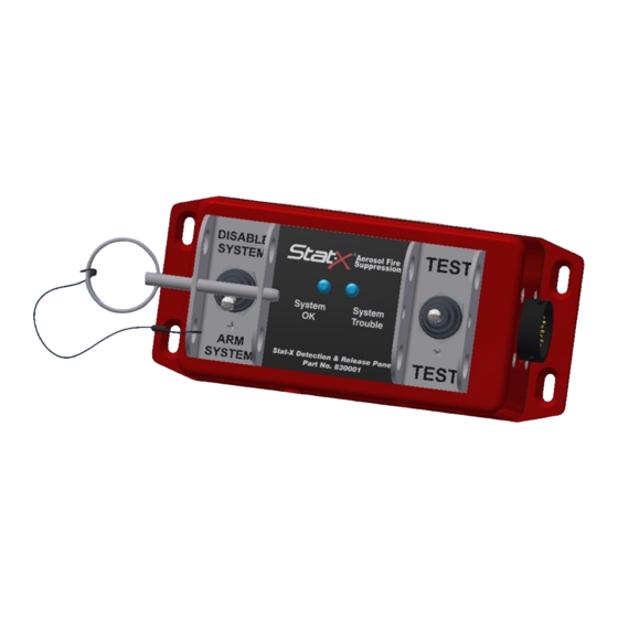
Figure 3 - SDRP Labeling The SDRP panel includes two detection zones and two releasing zones. The SDRP can be ordered in one of two programming configurations. Fireaway Inc. Version 1 5852 Baker Road... - Page 7 A single dedicated Manual Input Switch will also actuate both actuation zones. Detection Zones and Actuation zones cables are identified at the SDRP primary cable with a white label and colored ty-wraps. Figure 4 - SDRP mounting hole pattern Fireaway Inc.
- Page 8 SDRP Cable Harness Assembly The SDRP Cable Harness PN 830006 provides the connection between the SDRP and field wiring. The SDRP Cable Harness is available in two separate configurations – pre- terminated and unterminated. The pre-terminated version PN 830006 uses Deutsch DTM series connectors and a single MIL-Std circular connector.
-
Page 9: Alarm Test Module
The Alarm Module also provides the field service technician the ability to “live test” the SDRP panel and detection circuitry. When a detection circuit “closes” in Alarm, the Alarm Module senses the electrical load and simulates a system actuation. - Page 10 Switch uses a rugged, proven MIL-26482 metal shell connector to link the manual switch to the SDRP panel manual release input circuit. The normally open toggle switch used with the Manual Release Switch is protected by a labeled and latching toggle guard and stainless steel protective bracket.
- Page 11 End of Line device completing a loop back to the SDRP. If a Fire occurs, the outer and inner insulating jackets of the linear thermal wire melt allowing the individual conductors of the linear thermal wire to electrically “short”...
- Page 12 SDRP. If a fire occurs, the normally open contacts in the spot thermal close. This change in electrical resistance is interpreted by the SDRP as a fire condition.
- Page 13 Deutsch connector with an over molded 470k ohm resistor. The EOL provides a high resistance closed loop to each of the SDRP panel’s two detection circuits. A break or open in the circuit indicates a Trouble condition to the SDRP.
- Page 14 Detection Zone Field Wiring Field wiring used to connect between the SDRP and each spot thermal detector must be at a minimum UL Listed Plenum wire, 18 awg. Parallel field wiring is used between detectors. Detection field wiring must be protected in emt/conduit between each detector.
- Page 15 Figure 14 - Sample Actuation Circuit Wiring • Field wiring used to connect between the SDRP and each Stat-X generator must be at a minimum UL Listed Plenum wire, 18 awg. series field wiring is used between generators which is easily supervised by the SDRP. Parallel field wiring is acceptable but must be protected in emt/conduit as individual Stat-X generators are not supervised by the SDRP.
-
Page 16: Inspection And Maintenance
4. Hazard Analysis Refer to the current Stat-X owner’s manual PN19001 for generator installation requirements. 5. Inspection and Maintenance The SDRP panel is designed to be simple and reliable. Inspection and maintenance consists of the following: Daily Inspection if possible With the SDRP panel in “Armed”... - Page 17 -- The SDRP System is now operational – SDRP Internal Battery Replacement Procedure The batteries used with the SDRP are a lithium thionyl chloride chemistry. They cannot be recharged. Only use our PN 830009 as a replacement. 1. See figures #10 & #11 below.
- Page 18 Figure 16 - SDRP battery replacement data to be completed annually when batteries are replaced Fireaway Inc. Version 1 5852 Baker Road 10/2017 Minnetonka, MN 55345 P/N 19112...
-
Page 19: System Alarms And Troubleshooting
6. System Alarms and Troubleshooting Normal Operating Condition Flip the TEST toggle Switch to Test the SDRP system … System OK – Green LED ON Front Panel Display System Trouble – Yellow LED OFF Indicates Status Detection Field Wiring Continuous circuit with correct resistance... - Page 20 System Trouble – Yellow ON Indicates Status Possible Open Condition • Check to see if SDRP to field wiring circular connector is tight and connected Detection Field Wiring Problem • Check to see if end of line device is in place •...
-
Page 21: System Parts List And Replacement Parts List
7. System Parts List and Replacement Parts List Part Component Description Number 830001 Control Panel, SDRP, Battery Powered Panel, 830002 Module, Test, 830003 Switch, Toggle, Manual Release, 830006 Cable Assy, SDRP, Battery Powered Panel, (24” Unterminated Actuation Leads) 830007 EOL Assy, Detection, Class B, Deutsch... -
Page 22: Actuation Wiring
Actuation Wiring - The actuation circuit wiring is critical to the proper operation of the SDRP - Take care in making and securing all electrical connections - Water and corrosive atmospheres are never good for electrical circuits. Take care to...
Need help?
Do you have a question about the SDRP and is the answer not in the manual?
Questions and answers