Table of Contents
Advertisement
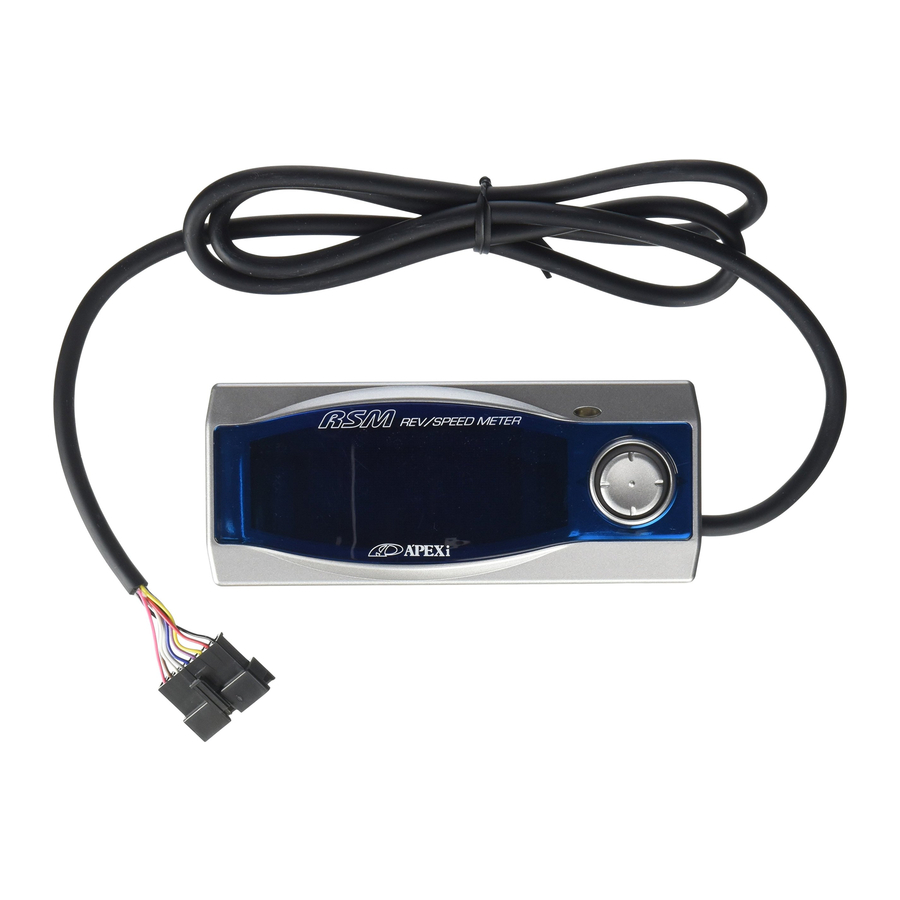
REV/SPEED METER
Vehicle Specific Wiring Diagram
●This wiring diagram booklet is designed for use with the
REV SPEED METER 405-A912/405-A916.
Please be sure to read the instruction manual for the
REV SPEED METER before performing installation.
●The REV SPEED METER requires both the Instruction
Manual and the Wiring Diagram for proper
●Even though a vehicle is listed in this manual, there is a
possibility that the unit will not operate properly due to
modifications on the vehicle, special model differences,
model changes, or other factors.
This manual is accurate up until Mar. 2008.
Please contact an Apex dealer for newer applications.
1
Advertisement
Table of Contents

Related Manuals for APEXi REV SPEED METER 405-A912

Summary of Contents for APEXi REV SPEED METER 405-A912
- Page 1 REV/SPEED METER Vehicle Specific Wiring Diagram ●This wiring diagram booklet is designed for use with the REV SPEED METER 405-A912/405-A916. Please be sure to read the instruction manual for the REV SPEED METER before performing installation. ●The REV SPEED METER requires both the Instruction Manual and the Wiring Diagram for proper ●Even though a vehicle is listed in this manual, there is a...
-
Page 2: Table Of Contents
■Table of Contents ■To begin ■Installation Precautions ■ECU Location Diagram ■How to View the ECU Diagrams ■Installation Diagram Selection Tak ■Connection Diagram (1)(2) ■Connection Diagram (3)(4) ■Connection Diagram (5)(6) ■TOYOTA ●Application Chart ●ECU Diagram ■NISSAN ●Application Chart ●ECU Diagram ■HONDA ●Application Chart ●ECU Diagram ■MITSUBISHI... -
Page 3: To Begin
■To Begin Please read the safety precautions in the Instruction Manual before proceeding with installation. Glossary of Safety Terms are outlined in the Instruction Manual In this manual, the Electronic Control Unit is called the ECU. Caution ! ●Installation of this unit should ONLY be performed by a trained professional. -
Page 4: Installation Precautions
■Installation Precautions ●Do not use electro taps in the installation of this product. Electro taps can become loose over time causing the unit to malfunction. This can also lead to vehicle and product damage. Be sure to use wire crimpers and the included splices for a secure connection. ●Be sure that the harness is not exposed to metal. - Page 5 ■ECU Arrangement Diagram ●Perform installation by referring to the symbols in the corresponding columns of the tables of applicable models on and after page 10 P L D B F E A C N M G O A : Lower part of the passenger seat dash side B : Right side of the glove box C : Foot position of the passenger seat D : Inner part of the glove box...
- Page 6 ■How to Refer to the ECU Terminal Arrangement Diagram This ECU terminal arrangement diagram is viewed from the direction of the arrow. The direction of the ECU varies depending upon the vehicle. Perform the installation work after confirming the connector shape and the number of pins.
-
Page 7: Installation Diagram Selection Tak
■Installation Diagram Selection Table ●Vehicles not listed below will use Connection Diagram (1) or (2). HONDA Name Type S2000 AP1 CF4 Torneo CF3 CF4 Accord CF3 CF7 Accord Wagon CF6 RA7 RA6 Odyssey RA4 RA3 GD4 GD3 GD2 GD1 GD9 GD8... - Page 8 ■Connection Diagram (1) When NOT Cutting Speed Limiter IG Power Ground Speed Purple: Speed 1 Input ■Connection Diagram (2) When Cutting Speed Limiter IG Power Ground Speed ECU Red: IG Power Yellow: RPM Black: Ground ECU Red: IG Power Yellow: RPM Black: Ground Pink: Speed 1 Output Purple: Speed 1 Input...
-
Page 9: Connection Diagram (1)
■Connection Diagram (3) IG Power Ground Speed Brown: Speed 2 Output ■Connection Diagram (4) IG Power Ground Speed Meter Signal Open Brown: Speed 2 Output ECU Red: IG Power Yellow: RPM Black: Ground Purple: Speed 1 Input ECU Red: IG Power Yellow: RPM Black: Ground Purple: Speed 1 Input... -
Page 10: Application Chart
■Application Chart (TOYOTA) Name Type Engine JZZ30 1JZ−GTE MZ20 7M−GTE Soarer 1G−GTE GZ20 1G−GE JZX100 1JZ−GTE (※5) 1JZ−GTE JZX90 1JZ−GTE Mark II/ Chaser/ 1JZ−GE Cresta 1JZ−GTE JZX81 1JZ−GE 1G−GTE GX81 1G−GE ※5: JZX 100 : For MarkⅡ,incompatible up to model year Year Notes M/T... - Page 11 Name Type Engine 2JZ−GTE JZA80 2JZ−GE JZA70 1JZ−GTE Supra MA70 7M−GTE 1G−GTE GA70 1G−GE SXE10 3S−GE Altezza ZZW30 1ZZ−FE MR-S 3S−GTE 3S−GE SW20 3S−GTE 3S−GE 4A−GZE AW11 4A−GE ZZT230 1ZZ−FE ST205 3S−GTE 3S−GE ST203 ST202 3S−FE Celica ST185 3S−GTE ST182 3S−GE...
- Page 12 Name Type Engine 3S−GE ST207 Curren ST206 3S−FE 3S−GE ST203 Carina ED ST202 Corona EXIV 3S−FE ST215W 3S−GTE ST215G 3S−GE ST21#G 3S−FE ST195G 3S−GE Caldina ST195G 3S−FE ST191G ST190G 4S−FE Year Notes ‘94.1∼‘98.7 M/T ‘96.6∼‘98.7 A/T M/T E ‘95.10∼‘96.5 A/T・w/ TRC A/T・w/o TRC w/TRC ‘94.1∼‘95.9...
- Page 13 Name Type Engine 4A−GE AE101 4A−FE Corolla FX AE92 4A−GE 4A−GE AE111 4A−FE AE110 5A−FE Corolla 4A−GE Sprinter AE101 4A−FE AE92 4A−GE 4A−GE AE111 4A−FE AE110 5A−FE 4A−GZE AE101 4A−GE Corolla Levin 4A−FE Sprinter Trueno 4A−GZE AE92 4A−GE AE86 4A−GEU 4A−GE...
- Page 14 Name Type Engine ACA2#W 1AZ−FSE ZCA26W 1ZZ−FE ZCA25W SXA1#G 3S−FE SXA11W RAV4 3S−GE SXA10W SXA11G 3S−FE SXA10G NCP13 1NZ−FE NCP15 2NZ−FE NCP10 SCP10 1SZ−FE Vitz NCP13 1NZ−FE NCP15 2NZ−FE NCP10 SCP10 1SZ−FE NCP25 1NZ−FE NCP21 Fun Cargo NCP20 2NZ−FE NCP30 2NZ−FE...
- Page 15 Name Type Engine NCP16 2NZ−FE NCP12 1NZ−FE SCP11 1SZ−FE Platz NCP16 2NZ−FE NCP12 1NZ−FE SCP11 1SZ−FE ZZE12# 1ZZ−FE NZE124 1NZ−FE NZE121 Corolla ZZE12# 1ZZ−FE NZE124 1NZ−FE NZE121 ZZE123G 2ZZ−GE ZZE122G 1ZZ−FE NZE124G 1NZ−FE Corolla NZE121G Fielder ZZE123G 2ZZ−GE ZZE122G 1ZZ−FE NZE124G...
- Page 16 ■ECU Diagram (TOYOTA) T1-a Ground Speed T3-a Speed Ground T4-b Speed Ground T5-b Speed Ground T5-d Speed Ground T2-a Ground IG Power T4-a Ground IG Power T5-a IG Power Ground T5-c IG Power Ground T6-a Ground IG Power Speed IG Power Speed IG Power Speed IG Power...
- Page 17 T6-b Speed IG Power Ground T8-a Speed IG Power Ground T8-c Speed Ground T9-a Ground T9-b Ground T7-a Ground T8-b Ground T8-d IG Power Ground Speed Speed Speed IG Power Speed IG Power Speed IG Power IG Power IG Power...
- Page 18 T10-a T10-b T10-c T10-d Ground T11-a Ground Ground Speed IG Power Speed Ground Ground Speed Speed Speed IG Power IG Power IG Power IG Power...
- Page 19 ■Application Chart (NISSAN) Name Type Engine G50 VH45DE President G50 VH45DE Infiniti Q45 FGY33 VH41DE Cima Ⅲ FHY33 VQ30DET FGY32 VH41DE Cima Ⅱ FPY32 VG30DET VG30DET Cima Ⅰ FPY31 VG30DE VG30DETT Z32 VG30DE Fairlady Z VG30DET Z31 VG30DE RB20DET VQ30DET Y33...
- Page 20 Name Type Engine VQ25DD A33 VQ20DE VQ30DE VQ25DE VQ20DE A32 Cefiro VQ30DE VQ25DE VQ20DE RB20DET A31 RB20DE RB25DE RB25DET C35 RB25DE RB20DE RB25DET Laurel C34 RB25DE RB20DE RB20DET C33 RB20DE RB26DETT R34 RB25DET RB26DETT R33 RB25DET RB25DE RB26DETT Skyline RB25DE R32...
- Page 21 Name Type Engine QR20DD Blue Bird QG18DE G10 Sylphy QG15DE SR20VE U14 SR20DE SR18DE SR20DET U13 SR20DE Blue Bird SR18DE SR20DET SR20DE U12 CA18DET CA18DE SR20DET S15 SR20DE SR20DET S14 SR20DE Silvia SR20DET PS13 SR20DE CA18DET S13 CA18DE SR20DET SR20DE RPS13...
- Page 22 Name Type Engine SR20VE SR20DE P11 SR18DE Primera SR20DE P10 SR18DE SR20VE Y11 Wing Road QG18DE QG15DE SR20DET W11 SR20DE SR20DET Avenir W10 SR20DE SR18DE B15 SR16VE B14 Sunny SR18DE B13 B13 SR18DE NX Coupe CG13DE K11 March CG10DE Z10 CG13DE...
-
Page 23: Ecu Diagram
■ECU Diagram (NISSAN) N1-a Speed N3-a Speed IG Power N4-a Speed N6-a 12p 12p 19p Speed Ground N8-a Ground N2-a Ground IG Power N3-b Ground N5-a Ground IG Power N7-a IG Power N8-b Ground IG Power Speed Ground IG Power Speed Speed Ground... - Page 24 N8-c N8-d Speed Ground Speed Ground IG Power IG Power N9-a IG Power Speed Ground...
-
Page 25: Application Chart
■Application Chart (HONDA) Name Type Engine NA2 C32B NSX NA1 C30A S2000 AP1 F20C KA9 C35A Legend KA8 C32A KA7 UA2 G25A UA1 G20A Inspire CC2 G25A CB5 G20A BB8 BB6 H22A Prelude BB4 BB1 CF4 F20B Torneo CF3 F18B CF4... - Page 26 Name Type Engine DC5 K20A Integra DC2 (including the B18C DB8 ’98 specification) DA6 B16A EP3 K20A EK9 B16B EK4 B16A Civic EK3 D15B EG6 B16A EG4 D15B EF9 B16A RA7 RA6 F23A RA4 Odyssey RA3 RA2 F22B RA1 Adj: Speed Pulse Adjust Setting ※Please refer to the instruction manual for setting procedures Year Setting...
- Page 27 Name Type Engine EG2 B16A CR−X EG1 D15B EF8 B16A RD2 CR−V B20B RD1 RH2 S−MX B20B RH1 RF2 B20B STEP WGN RF1 JB2 E07Z JB1 Life JA4 E07A GA4 D15B Capa Z PA1 E07Z GD4 L15A GD3 F i t GD2...
-
Page 28: Ecu Diagram
■ECU Diagram (HONDA) H1-a IG Power Ground Speed H3-a IG Power Ground Speed H3-c IG Power Speed Ground H4-b Ground IG Power Speed H5-b IG Power Speed Ground H2-a ※There might not be free space of connector IG Power Ground H3-b IG Power Speed... - Page 29 H7-a IG Power Ground Speed H8-a Speed IG Power Ground H9-a Ground Speed IG Power H10-a IG Power Ground H7-b Meter Signal IG Power Ground H8-b IG Power Ground Speed Meter Signal Speed Speed...
- Page 30 ■Application Chart (MITSUBISHI) Name Type Engine GTO Z16A 6G72 DE3A 6A12 FTO DE2A 4G93 EC5W 6A13 Legnum EC5A 6A13 Galant E84A 6A12 E39A 4G63 D32A 4G63 Eclipse D27A Lancer CT9A 4G63 EvolutionⅨ Lancer CT9A 4G63 EvolutionⅧ Lancer CT9A 4G63 EvolutionⅦ CP9A...
- Page 31 Name Type Engine CM5A 4G93 CJ4A Mirage 4G92 CA4A N94W Chariot 4G64 Grandis N84W V75W V65W 6G74 Pajero V25W V23W 6G72 H77W 4G94 H76W 4G93 Pajero Io H6#W H72W 4G94 H57A 4A31 Pajero Jr. H58A 4A30 Pajero Mini H53A N74WG 4G64...
- Page 32 ■ECU Diagram (MITSUBISHI) M1-a Ground IG Power M3-a IG Power Ground M5-a IG Power Speed Ground M7-a Ground IG Power M2-a IG Power Ground Speed M4-a IG Power Speed Speed M6-a IG Power Ground Speed Speed Ground Speed...
- Page 33 ■Application Chart (MAZDA) Name Type Engine JC3S 13B−REW JC3SE Eunos Cosmo JCES 20B−REW JCESE FD3S 13B−REW RX−7 FC3S 13B BP−VE(RS) NB8C BP−ZE(RS) NB6C B6−ZE(RS) Roadster NA8C BP−ZE ZL−DE BJ5P ZL−VE Familia BJ3P B3−ME BG8Z BP−ZET Familia S BJFW FS−ZE Wagon Year Notes ‘94.3∼‘95.8...
- Page 34 Name Type Engine B5E DW5W B5−ME Demio B3E DW3W B3−ME MD21S K6A T/C AZ Wagon MD11S F6A T/C Year Notes ‘99.12∼‘02.7 ‘96.8∼‘99.11 I ‘99.12∼‘02.7 ‘96.8∼‘99.11 L ‘98.10∼‘00.11 Diagram Z8−a Z2−b Z8−a Z2−b Z7−a...
-
Page 35: Ecu Diagram
■ECU Diagram (MAZDA) Z1-a Ground IG Power ※Take Speed Signal from Cruise Control (Z1-CC) ※When cutting Speed Limiter, cut the 180k signal wire and cover in electrical tape Z2-a Ground 180k Signal ※Take Speed Signal from Cruise Control (Z2-CC) ※ When cutting Speed Limiter, cut the 180k signal wire and cover in electrical tape Z2-b Ground... - Page 36 Z3-c Ground Speed Z3-e Speed Ground Z5-a Speed Ground IG Power Z6-a Speed Ground IG Power Z8-a Ground IG Power Speed Z3-d Ground IG Power Z4-a Speed IG Power Z5-b Ground Speed Z7-a IG Power Speed Z9-a IG Power Speed Speed IG Power IG Power...
-
Page 37: Application Chart
■Application Chart (SUBARU) Name Type Engine BE9 EJ254 EJ208 EJ206 Legacy B4 EJ204 BE5 EJ208 EJ204 EJ208 EJ206 Legacy EJ204 BH5 Touring Wagon EJ208 EJ206 EJ204 EJ20R BD5 EJ20D BG5 EJ20H Legacy BD9 EJ25D BG9 BC5 EJ20G BF5 GDB EJ207 GGB... - Page 38 Name Type Engine SG9 EJ255 EJ205 SG5 Forester EJ202 EJ205 SF5 EJ20G EN07 KK4 Vivio KK3 EN07Z EN07X Year Notes STi Ver. ‘04.2∼‘04.12 M/T A/T ‘02.2∼※ C M/T A/T ‘98.9∼‘02.1 ‘97.2∼‘98.8 DOHC・S/C ‘97.5∼‘98.10 A/T S/C・M/T H ‘96.11∼‘98.10 SOHC・S/C A/T SOHC・S/C ‘92.3∼‘96.10...
-
Page 39: Ecu Diagram
■ECU Diagram (SUBARU) F1-a Speed Ground F1-c Ground IG Power F2-a Speed Ground F3-a Speed F5-a Ground IG Power Speed F1-b IG Power F1-d Speed F2-b IG Power Speed F4-a Ground IG Power Ground F5-b Ground Speed IG Power Ground Ground Speed IG Power... - Page 40 F5-c IG Power Ground Speed F6-a IG Power F6-b IG Power F6-c IG Power F7-a IG Power F5-d Speed Speed Ground Speed Ground Speed Ground Ground Speed IG Power Ground...
-
Page 41: Application Chart
■Application Chart (SUZUKI) Name Type Engine HA22S K6A T/C HA12S F6A T/C Alto Works HA21S K6A T/C HB21S HA11S F6A T/C HB11S EA21R K6A T/C Cappuccino EA11R F6A T/C MC21S K6A T/C MC11S F6A T/C CT51S K6A T/C Wagon R CV51S... -
Page 42: Ecu Diagram
■ECU Diagram (SUZUKI) S1-a Ground IG Power Speed S3-a Ground Speed S5-a IG Power Ground Speed S6-a Ground IG power Speed Ground S2-a IG Power S4-a Ground IG Power Speed Ground Speed IG Power Speed IG Power... -
Page 43: Application Chart
■Application Chart (ISUZU) Name Type Engine Year Notes Diagram UBS25 6VD1 E I1−a ‘91.12∼‘98.1 Big Horn ■ECU Diagram (ISUZU) I1-a IG Power Speed Ground... - Page 44 Notes The contents of this document are subject to change without prior notice 2. The contents of this document have been prepared with extreme care. However, if you find, error, or other fault, please inform us of it 3. A part or all of this document may not be reproduced in any form without prior written permission, and also may not used without the prior written permission of Apex Co., Ltd.
Need help?
Do you have a question about the REV SPEED METER 405-A912 and is the answer not in the manual?
Questions and answers