Table of Contents
Advertisement
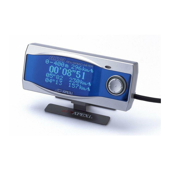
REV SPEED METER
Instruction Manual
Thank you for purchasing this unit. Please
read this manual to ensure proper use of
this product. Also, be sure to keep this
manual in a safe place for future reference.
Be sure to include this instruction manual
when transferring ownership of this product.
Product Name
Product Code
Applications
Features
REV / SPEED METER
405-A912 / 405-A916
Only for Vehicles listed in the Wiring
Diagram Booklet
Engine Speed and RPM, Travel Distance
Battery Voltage
0-100,200,400m Acceleration
0-100,200,300km/h Acceleration
Preset 0-250km/h Mid-Range Accel., etc.
Advertisement
Chapters
Table of Contents

Related Manuals for APEXi RSM 405-A912


Summary of Contents for APEXi RSM 405-A912
-
Page 1: Instruction Manual
REV SPEED METER Instruction Manual Thank you for purchasing this unit. Please read this manual to ensure proper use of this product. Also, be sure to keep this manual in a safe place for future reference. Be sure to include this instruction manual when transferring ownership of this product. -
Page 2: Table Of Contents
Contents Chapter 1 To Begin ________________________________________________________ 4 Safety Precautions _________________________________________________________________ 6 Functions ________________________________________________ 8 Part Names and Functions Parts List......................8 Part Names ......................9 Glossary......................... 9 _________________________________________________ 10 About the Optional Parts Chapter 2 Initial Setting ________________________________________________ 12 Before Using this Product _______________________________________________________ 13 Initial Setting Table Flow of Initial Setting .................... -
Page 3: Chapter 1 To Begin
Chapter 1 To Begin _________________________________ 4 Safety Precautions __________________________________ 6 Product Features _________________________ 8 Part Names and Functions ................8 Parts List ................9 Part Names ................9 Glossary ___________________________ 10 About the Optional Parts... -
Page 4: Safety Precautions
Safety Precautions ■ Glossary Display Meanings safe this product, be sure to read Failure to do so may result the Safety Precautions. WARNING in death or severe injury to ! Keep the manual in a safe the user and others. place after use for future reference. - Page 5 WARNING ! ●Never operate this unit while driving This may lead to accidents. ●Always remove the negative terminal of the battery before attempting installation. Failure to do so may result in electrical fires and engine fire. ●Never pull hard on the coupler, be sure to correctly unclip the coupler. Failure to do so may result in loose wire electrical shorts and electrical fire.
-
Page 6: Functions
FUNCTIONS The RSM (Rev Speed Meter) is a multi function measuring device designed to measure and monitor vehicle speed, RPM, 0-400m time, mid range acceleration, estimated horsepower, as well as acceleration G.(Using optional G Sensor) ■Easy to Read VFD (Vacuum Fluorescent Display) The RSM utilizes and easy to read VFD screen in a highly stylish case which also complements the cockpit interior. - Page 7 ■Various Measurements/ Display Parameters and Best Time Recording Engine RPM, Speed, Travel Distance, and Battery Voltage can be displayed in real time Graph Mode. Numerical Mode and Meter Mode allows Peak Hold function while the Graph Mode allows for Replay. In addition, the unit can measure Travel Distances, 0-100m/200m/400m times and 0-100km/h/200km/h/300km/h times.
-
Page 8: Part Names And Functions
Part Names and Functions Parts List ■ Be sure to check the contents before attempting installation. Please notify your dealer of purchase for any missing or broken parts BEFORE attempting installation. 1. Control Unit 4. Diagram Instruction Manual Wiring Manual 2. -
Page 9: Glossary
Part Names ■ Light Sensor VFD Display Screen (CDS Sensor) Multi-directional Button (With Center Push Function) G Sensor Connector Port How to Operate Main Button Switch ■ Push UP Push DOWN Push LEFT Push RIGHT Push CENTER About the Pop-Up Menus ●... -
Page 10: About The Optional Parts
About the Optional Parts ■G Sensor for Accurate Power Readings By utilizing the optional G Sensor, the user can monitor 4-way G movement as well as highly accurate power measurements. Usually, when measuring 0-400m times through the speed sensor signal alone, the meter will end measurement too early (shorter distance) due to wheel-spin Using the G Sensor will compensate for the... - Page 11 Chapter 2 Initial Settings ______________________ 12 Before Using this Product _____________________________ 13 Initial Setting Table ............13 Flow of Initial Setting ..14 About a part of Nissan car and the HONDA car ____________________________ 15 Other Initial Settings 【TIRE】 ........... 15 Tire Size Correction Vehicle Weight Input 【WGHT】........
-
Page 12: Before Using This Product
Before Using this Product Install the unit Please refer to the separate Vehicle Specific Wiring Diagram Booklet for proper installation on the vehicle. ● Be sure that your vehicle is listed in the wiring diagrams. Do NOT install on any vehicle not listed in the wiring diagram booklet. Perform Initial Setting 2... -
Page 13: Flow Of Initial Setting
Initial Setting To next page Flow of Initial Setting It initializes it as follows before this product is used. Please note that the setting is different in a part of Nissan Motor car and the HONDA car. Please refer to the setting of P50 according to the model for the operation method. Cylinder Number Setting P50【etc.】→【Car... -
Page 14: About A Part Of Nissan Car And The Honda Car
Continuation from last page About a part of Nissan car and the HONDA car In Nissan and the HONDA car of the following table correspondence, it refers to a table, and the pulse setting and the pulse adjustment setting of initialization are done. ■A part of Nissan car Pulse Name... -
Page 15: Other Initial Settings
Other Initial Settings For use when the factory tire sizes are changed Tire Size Diameter Corr. P50【etc.】→【Car Select】TIRE Formula New Tire Diameter ×100 Correction Value = Factory Tire Diameter Please refer to tire manufacturer data for diameter specs, or measure the tire Ex) Skyline GT-R (BNR32) Factory Tire 225/50 R16... -
Page 16: Using Optional Outputs
Using Outputs Activate Outputs at Desired RPM Levels RPM Output P48【etc.】→【Output Set】RvO This function allows an open collector transistor to turn ON when RPM exceeds a preset value. 【Default Value】3000rpm (MAX 12V. 200mA) If the RPM output is set to 7500rpm, the lamp will illuminate when rpm exceeds 7500rpm. -
Page 17: Using The Warning Display
Using the Warning Display Numerical Values will flash when HIGHER than the preset engine RPM (Monitor Mode RPM Warning Display P48【etc.】→【Output Set】RvW Flashes 2 Channel Monitor Mode Display The Numerical value will flash when HIGHER than the preset level during Monitor Mode, and 1 Channel Analog + Numerical Display 【Default】5000rpm Numerical Values will flash when HIGHER than the preset speed (Monitor Mode) -
Page 18: Chapter 3 Operation
Chapter 3 Operation Function and Operation _________________________ 20 Monitor Mode Overview __________________________22 Measure Mode Overview ________________________ 23 Etc. Mode Settings ______________________________ 23... -
Page 19: Function And Operation
Function and Operation Monitor Mode Displays Sensor Data Engine RPM, Speed, Battery Voltage, Trabel Distance, 4-way Acceleration Main Menu Measurement (When The RSM utilizes 3 Main using optional G Menus easy Sensor) navigation Measure Mode Measure Various Parameters 0-100,200,400m acceleration 0-100,200,300km/h acceleration Preset Mid-Range... - Page 20 ■[1Channel~4Channel] Display Parameters 1. Rev......Engine RPM 2. Spd ......Vehicle Speed 3. Trp ......Travel Distance 4. F/R ....Front/Rear Acceleration Measurement 5. R/L ....Left/Right Acceleration Measurement 6. Bat...... Battery Voltage ■Rev.-[Y] Display Parameter Displays a plotted graph with Engine RPM as the horizontal axis. 1.
-
Page 21: Monitor Mode Overview
Main Menu【Monitor】 Monitor Mode Overview 【Displays between1~4 parameters】 P26【Monitor】→【1Channel】~【4Channel】 [Parameter Glossary] 1. Rev....Engine RPM 2. Spd....Vehicle Speed 3. Trp ....Travel Distance 4. F/R ....Front/Rear Acceleration Measurement (Using G Sensor) 5. R/L ....Right/Left Acceleration Measurement (Using G Sensor) 6. -
Page 22: Measure Mode Overview
Main Menu【Measure】 Measure Mode Overview 1. 0-*00m....................P34 0-100,200,400m Acceleration Measurement 2. 0-*00k ....................P36 0-100,200,300km/h Acceleration Overview 3. **-**k ....................P38 Preset Mid-Range Acceleration Overview 4. STOP-W....................P40 Stop Watch (Lap/Split) 5. POWER .....................P42 Power Measurement 6. LOSS-P ....................P43 Loss Power Measurement Main Menu【etc.】 Etc. -
Page 23: Chapter 4 Monitor Mode【Monitor
Chapter 4 Monitor Mode Choosing between 1~4 channels _________________ 26 Graph Mode plotting RPM as Horizontal Axis _______ 30 Graph Mode plotting Front Rear Left Right Acceleration 31... -
Page 24: Display Parameters
【monitor】→【1Channel】~【4Channel】 Choosing Between 1~4 Channels 1~4 Channels can be selected from the 6 parameters below. The data can be displayed in Numerical, Analog, and Graph Modes. Each mode allows a Pause function. Also, Numerical and Analog modes have Peak Hold, while the Graph Mode has Replay. 【CAUTION】Replay Mode will replay the most recent memorized data Despite changing any of the parameters. - Page 25 To next page Return 3 Select data from parameter screen Pr ■When selecting【1 Channel】 (1) Selecting Parameter In the Display Parameter Mode, press the Select button up or down. Selected parameter will illuminate. (2) Display Parameter Press the button to the right, or push the Enter Display Parameters center of the button and select【Nx】from...
- Page 26 Continuation from last page Return 4 Selected Parameters will Display Pr Choosing【Nx】on Pop Up Menu will toggle Nx between (Numerical Display) → Numerical Display Nx (Graph Display) → (Analog Display) → (Numerical Display) etc... Nx Analog Display Graph Display Meter Mode can display up to 2 parameters.
- Page 27 【monitor】→【1Channel】~【4Channel】 Choosing Between 1~4 Channels Graph Display Functions ● Examples is for【1 channel】 ※ ■Replay Function Start ●Normal Mode Pause Start Replay (Right Scroll) Right Scroll Left Scroll Reset Start Memory Pause Right Scroll Start Pause Left Scroll ■Memory Function Stop Memory ■Pause Remaining Time...
- Page 28 【monitor】→【Rev.-[Y]】 Graph Mode plotting RPM as Horizontal Axis Return 1 2 Select【Monitor】from the Select【Rev.-[Y]】 Main Menu In Monitor Menu Pr Select Enter Select Enter Nx Return Return 3 4 Select data from the Selected data will Pr Parameter Selection display Menu Pr...
- Page 29 【monitor】→【G-FR/RL】 Graph Mode plotting Fr/Rr/Lt/Rt Acceleration Return 1 2 Select【Monitor】from the Select【G-FR/RL】 【Main Menu In Monitor Mode Pr Select Enter Select Enter Nx Return 3 Items will display Pr Push the center button and activate【Nx】on the Pop Up Menu to toggle between (1 point display)→ (10 point display)→(Ghost Map Trace)→(1 point display)...etc..
-
Page 30: 0-100,200,400M Acceleration
Chapter 5 Measure Mode 0-100,200,400m Acceleration ____________________ 34 0-100,200,300km/h Acceleration __________________ 36 Preset Mid Range Acceleration ___________________ 38 Stop watch (Lap. Split) Measurement ______________ 40 Power Measurement ____________________________42 Loss Power Input/Measurement __________________43... -
Page 31: 0-100,200,400M Acceleration
【measure】→【0-*00m】 0-100,200,400m Acceleration Current Speed (During) Measurement Final Speed (After) Distance Current Time (During) Current Time (After) 200m Time 200m Speed 100m Time 100m Speed Return 1 2 Select【measure】from the Select 【0-*00m】 Main Menu from Measure Mode Select Select Pr Enter Enter Main Menu... - Page 32 ② Measure (1) Prepare Pressing the button DOWN will show [Ready!] to flash on screen placing the unit in stand-by mode. (If pressed during driving, [Ready!] will appear after the car has stopped. Real Measuring Mode Time display of speed will occur during driving.) (2) Measure Measure During Stand-By, when the unit receives an input signal from...
-
Page 33: 0-100,200,300Km/H Acceleration
【measure】→【0-*00k】 0-100,200,300km/h Acceleration Current Speed (During) Measurement 300km/h Travel Distance Distance Current Time (During) Final Time (After) 200km/h Time 200km/h Travel Distance 100km/h Time 100km/h Travel Distance Return 1 2 Select【measure】from the Select 【0-*00k】from Main Menu Measure Mode Select Select Pr... - Page 34 ② Measure (1) Prepare Pressing the button DOWN will show [Ready!] to flash on screen placing the unit in stand-by mode. (If pressed during driving, [Ready!] will appear after the car has stopped. Real Measuring Mode Time display of speed will occur during driving.) (2) Measure Measure During Stand-By, when the unit receives an input signal from...
-
Page 35: Preset Mid Range Acceleration 【**-**K
【measure】→【**-**k】 Preset Mid Range Acceleration Ending Speed Starting Speed Current Time (During) Final Time (After) Measurement Distance Current Speed Return 2 1 Select【measure】from the Select【**-**k】from Main Menu Main Menu Select Select Pr Enter Enter Main Menu Measure Menu Nx Return Screen will display **-**k Measuring Mode Pr... - Page 36 ② Measure (1) Prepare Pressing the button DOWN will show [Ready!] to flash on screen placing the unit in stand-by mode. (If pushed when above START speed, [Ready!] will flash when speed falls Measure Mode under START speed.) (2) Measure Measure During Stand-By,measurement will begin once vehicle speed exceeds the START speed.
-
Page 37: Stop-W
【measure】→【STOP-W】 Stop Watch (Lap/Split) Measurement Lap/Split Status Display Current Time (During Lap Mode) Lap Display (During Split Mode) Split Display Return 1 2 Select【measure】from the Select【STOP-W】from Main menu Measure mode Select Select Pr Enter Enter Main Menu Nx Measure Menu Return Screen will display Stop Watch Measuring Mode Pr... - Page 38 ●Multiple Time Measurement Stop Stop Start Start Reset Display Example Stop Stop Start Start ●Lap Time Measurement When selecting【lap】 Reset Display Example Stop Start ●Split Time Measurement When selecting【spl】 Reset Display Example Split Split Start Stop ■ Check Lap/Split Times Measurement】Press 【After Rc...
-
Page 39: Power Measurement Power
【measure】→【POWER】 Power Measurement (only available with optional G sensor) Return 1 2 Select【measure】from the Select【POWER】from 、 Main menu Measure mode Select Select Pr Enter Enter Main Menu Nx Measure Menu Return Screen will display Power Measure Mode Pr Current Power Peak Power Peak Power Current RPM... -
Page 40: Loss-P
【measure】→【LOSS-P】 To next page Loss Power Input/Measure (only for use with optional G Sensor) When using the optional G Sensor to measure Power, Loss Power values must be input. The table below lists some typical Loss Power data for vehicle categories. Choose the closest Loss Power data from below taking vehicle type, drive-train, and weight into consideration. - Page 41 Continuation from last page Return 1 2 Select【measure】from the Select【LOSS-P】from Main menu 。 Measure mode Select Select Pr Enter Enter Main Menu Nx Measure Menu Return Screen will display Loss Power Input/Measure Mode Pr Select Nx Change 1 Point Display Loss Power input Mode ■Input Loss Power 10 Point Display...
- Page 42 【measure】→【LOSS-P】 Loss Power Input/Measure ■ Measure Loss Power ● Secure a Safe Testing Road Measure on a long, flat road surface. (Avoid public roads when possible.) Any type of hill or curve will increase the resistance placed on the vehicle (ie. through tire friction, engine load) and prevent an accurate calculation.
- Page 43 Chapter 6 Etc. Mode Output Setting __________________________________48 Graph Scale Setting _____________________________49 Vehicle Specific Setting __________________________50 VFD Adjustment _________________________________51 G Sensor Calibration _____________________________52 Initialize All Data ________________________________53 Troubleshooting __________________________________ 54...
-
Page 44: Output Setting 【Output Set
【etc.】→【Output set】 Output Setting Rpm/Speed Output. RPM/Speed Warning Output Speed Limiter Cut Setting This section will set the RPM/Speed Output, RPM/Speed Warning Output, and Speed Limiter Cut Settings Return 1 2 Select【etc.】from the Select【Output Set】from 【Main Menu the Etc. Menu. Select Select Pr... -
Page 45: Graph Scale Setting 【Grph Scale
【etc.】→【Grph Scale】 Graph Scale Setting Changes the Analog and Graph Display Scales Return 1 2 Select【etc.】from the Select【Grph Scale】 Main Menu from the Etc. Menu. Select Select Pr Enter Enter Main Menu Nx Etc. Menu Return The screen will display Graph Scale Mode Pr... -
Page 46: Vehicle Specific Setting 【Car Select
【etc.】→【Car Select】 Vehicle Specific Setting Allows setting of largest value for Analog and Graph Displays. Return 1 2 Select【etc.】from the Select【Car Select】from Main Menu the Etc. Menu. Select Select Pr Enter Enter Main Menu Nx Etc. Menu Return The screen will display Vehicle Specific Settings. Pr... -
Page 47: Vfd Adjustment 【Vfd Bright
【etc.】→【VFD Bright】 VFD Adjustment This unit uses an internal light sensor to sense brightness, and adjusts VFD screen brightness automatically. The parameter reading【Day】is meant fro daytime,【Dim】is for dusk,【Nig】is for night time illumination. Adjustment should not be necessary during daytime. Return 1... -
Page 48: G Sensor Calibration
【etc.】→【Gsnsr Corr】 G Sensor Calibration This will calibrate the 0 point of the separately sold G sensor. This process must be performed to ensure accurate acceleration readings. Always perform this process when installing or moving the G Sensor. Return 1 2... -
Page 49: Initialize All Data 【Initialize
【etc.】→【Initialize】 Initialize All Data This function will initialize all stored data and return the unit to factory default settings. Return 1 2 Select【etc.】from the Select【Initialize】from Main Menu the Etc. Menu Select Select Pr Enter Enter Main Menu Etc. Menu Nx Return The Screen will display Initialize All Data Mode Pr... -
Page 50: Troubleshooting
Troubleshooting Power will not ●Is the battery connected? ●Are the ECU harness and signal harnesses connected? ●Is the RSM harness and signal harnesses connected? Fault connections can occur even when the harnesses seem to be connected. Double check all connectors, splices, and plugs. Unit does not ●Speed/RPM does not appear on screen display properly... - Page 51 Unit does not ●Acceleration Display is incorrect display properly ・Has the G Sensor been calibrated? (cont'd) ・Has the G Sensor been installed correctly? ●Power Measurement is incorrect ・Has the vehicle weight been input correctly?(P50) ・Has the G Sensor been calibrated? (P52) ・Has the G Sensor been installed correctly? ・Has Loss Power been input? (P43)...
- Page 52 Caution We reserve the right to change any part of this manual without prior notice. 1. We have made every effort possible to make this manual as accurate as 2. possible. However, we assume no responsibility for any errors resulting from typographical, model changes, regional differences, or other factors that may cause improper function.
Need help?
Do you have a question about the RSM 405-A912 and is the answer not in the manual?
Questions and answers