
Subscribe to Our Youtube Channel
Related Manuals for Nexcom NViS 1482 Series

Summary of Contents for Nexcom NViS 1482 Series
- Page 1 NEXCOM International Co., Ltd. Intelligent Digital Security Video Intelligent Surveillance NViS 1482 Series User Manual NEXCOM International Co., Ltd. www.nexcom.com Published November 2021...
-
Page 2: Table Of Contents
LAN1 Connector and USB 3.0 Ports ...........19 NViS 1482 Rear Panel ................4 LAN2 Connector and USB 3.0 Ports ...........19 Mechanical Dimensions ................5 SPI BIOS Update Connector ...............20 Mechanical Dimensions ................6 Copyright © 2021 NEXCOM International Co., Ltd. All Rights Reserved. NViS 1482 Series User Manual... - Page 3 Default Configuration ................44 Entering Setup ..................44 Legends ....................44 BIOS Setup Utility ..................46 Main ....................46 Advanced ..................47 Chipset ....................56 Security .....................61 Secure Boot ..................62 Boot ....................62 Copyright © 2021 NEXCOM International Co., Ltd. All Rights Reserved. NViS 1482 Series User Manual...
-
Page 4: Preface
No describes how to keep the system CE compliant. part of this manual may be reproduced, copied, translated or transmitted in any form or by any means without the prior written consent from NEXCOM Declaration of Conformity International Co., Ltd. -
Page 5: Rohs Compliance
(Cr6+) < 0.1% or 1,000ppm, Polybrominated biphenyls (PBB) < 0.1% or 1,000ppm, and Polybrominated diphenyl Ethers (PBDE) < 0.1% or 1,000ppm. In order to meet the RoHS compliant directives, NEXCOM has established an engineering and manufacturing task force to implement the introduction of green products. -
Page 6: Warranty And Rma
(manuals, cable, etc.) and any components from the card, such as CPU and RAM. If the components were suspected as part of the problems, ▪ If RMA goods can not be repaired, NEXCOM will return it to the customer please note clearly which components are included. Otherwise, NEXCOM without any charge. - Page 7 ESD workstation. If no such station is available, you can provide some ESD protection by wearing an antistatic wrist strap and attaching it to a metal part of the computer chassis. Copyright © 2021 NEXCOM International Co., Ltd. All Rights Reserved. NViS 1482 Series User Manual...
-
Page 8: Safety Information
There is a danger of explosion if battery is incorrectly replaced. Replace only with the same or equivalent type recommended by the manufacturer. Discard used batteries according to the manufacturer’s instructions. viii Copyright © 2021 NEXCOM International Co., Ltd. All Rights Reserved. NViS 1482 Series User Manual... -
Page 9: Safety Precautions
RECOMMENDED BY THE MANUFACTURER. DISCARD USED BATTERIES ACCORDING TO THE MANUFACTURER’S INSTRUCTIONS. 10. All cautions and warnings on the equipment should be noted. Copyright © 2021 NEXCOM International Co., Ltd. All Rights Reserved. NViS 1482 Series User Manual... -
Page 10: Technical Support And Assistance
Preface Technical Support and Assistance Conventions Used in this Manual 1. For the most updated information of NEXCOM products, visit NEXCOM’s Warning: website at www.nexcom.com. Information about certain situations, which if not observed, can cause personal injury. This will prevent injury to yourself 2. -
Page 11: Global Service Contact Information
16F, No.250, Sec. 2, Chongde Rd., Beijing, 100094, China Beitun Dist., Tel: +86-10-5704-2680 Taichung City 406, R.O.C. Fax: +86-10-5704-2681 Tel: +886-4-2249-1179 Email: sales@nexsec.cn Fax: +886-4-2249-1172 www.nexsec.cn Email: sales@nexaiot.com.tw www.nexaiot.com.tw Copyright © 2021 NEXCOM International Co., Ltd. All Rights Reserved. NViS 1482 Series User Manual... - Page 12 Room 603/604, Huiyinmingzun Plaza Bldg. 1, Tel: +81-3-5419-7830 No. 609, Yunlin East Rd., Fax: +81-3-5419-7832 Shanghai, 200062, China Email: sales@nexcom-jp.com Tel: +86-21-5278-5868 www.nexcom-jp.com Fax: +86-21-3251-6358 Email: renwang@nexcom.com.tw www.nexcom.cn Copyright © 2021 NEXCOM International Co., Ltd. All Rights Reserved. NViS 1482 Series User Manual...
-
Page 13: Package Contents
Preface Package Contents Before continuing, verify that the NViS 1482 series package that you received is complete. Your package should have all the items listed in the following table. NViS 1482 Item Part Number Name Description 10C00148200X0 NViS 1482 System... -
Page 14: Ordering Information
The following information below provides ordering information for the NViS 1482 series. NViS 1482 (P/N: 10C00148200X0) NViS1482 desktop SoC NVR with Intel ® Elkhart Lake platform built-in 8-port PoE Copyright © 2021 NEXCOM International Co., Ltd. All Rights Reserved. NViS 1482 Series User Manual... -
Page 15: Chapter 1: Product Introduction
Ethernet ▪ 1 x 2.5G Intel Ethernet ▪ 8 x 10/100 PoE (120W max PSE) ▪ Support TPM 2.0 onboard ▪ Support eMMC onboard (option) Copyright © 2021 NEXCOM International Co., Ltd. All Rights Reserved. NViS 1482 Series User Manual... -
Page 16: Hardware Specifications
- 802.3af support 8 ports @ 15W - 802.3at support 4 ports @30W ▪ 1 x 4DI/2DO (relay type) terminal block or 4DI/4DO GPIO DB15 port (option) Copyright © 2021 NEXCOM International Co., Ltd. All Rights Reserved. NViS 1482 Series User Manual... -
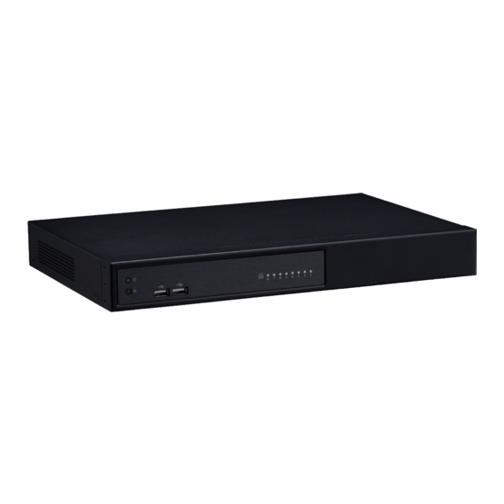
Page 17: Knowing Your Nvis 1482 Series
Used to connect USB 2.0 devices. PoE LAN LED Indicators Indicates the status of the LAN ports. 2x USB 2.0 Ports LED Indicators PoE LAN LED Indicators Copyright © 2021 NEXCOM International Co., Ltd. All Rights Reserved. NViS 1482 Series User Manual... -
Page 18: Nvis 1482 Rear Panel
RJ45 to PoE-enabled edge devices. Power Switch Press to power on the device. 54V DC Input Used to plug a DC power cord. Copyright © 2021 NEXCOM International Co., Ltd. All Rights Reserved. NViS 1482 Series User Manual... -
Page 19: Mechanical Dimensions
Chapter 1: Product Introduction Mechanical Dimensions Rackmount Model 366.00 192.80 224.50 3.00 28.70 360.00 16.00 44.00 16.00 6.00 465.00 482.80 Copyright © 2021 NEXCOM International Co., Ltd. All Rights Reserved. NViS 1482 Series User Manual... -
Page 20: Mechanical Dimensions
Chapter 1: Product Introduction Mechanical Dimensions Desktop Model 126.00 224.50 67.50 360.00 360.00 44.00 49.00 287.80 36.10 Copyright © 2021 NEXCOM International Co., Ltd. All Rights Reserved. NViS 1482 Series User Manual... -
Page 21: Mechanical Dimensions
Chapter 1: Product Introduction Mechanical Dimensions Wallmount Model 60.00 160.00 8.20 60.00 68.50 50.50 373.80 387.80 360.00 44.00 50.00 Copyright © 2021 NEXCOM International Co., Ltd. All Rights Reserved. NViS 1482 Series User Manual... -
Page 22: Chapter 2: Jumpers And Connectors
Static electricity can damage many of the electronic ▪ Use correct screws and do not over tighten screws. components. Humid environments tend to have less static electricity than Copyright © 2021 NEXCOM International Co., Ltd. All Rights Reserved. NViS 1482 Series User Manual... -
Page 23: Jumper Settings
(on) and open (off). Two-Pin Jumpers: Open (Left) and Short (Right) Three-Pin Jumpers: Pins 1 and 2 are Short Copyright © 2021 NEXCOM International Co., Ltd. All Rights Reserved. NViS 1482 Series User Manual... -
Page 24: Locations Of The Jumpers And Connectors
Locations of the Jumpers and Connectors The figure below shows the location of the jumpers and connectors. 32 31 30 29 32 31 FAN2 DIMM1 PWR_SW1 CN11 DIMM2 Copyright © 2021 NEXCOM International Co., Ltd. All Rights Reserved. NViS 1482 Series User Manual... -
Page 25: Jumpers
Chapter 2: Jumpers and Connectors Jumpers Clear CMOS Connector type: 1x3 3-pin header Connector location: JP1 Settings Normal Clear CMOS 1-2 On: default Copyright © 2021 NEXCOM International Co., Ltd. All Rights Reserved. NViS 1482 Series User Manual... -
Page 26: Connector Pin Definitions
Connector type: Phone Jack RJ45 2x4 Port PoE 54V Power-in Connector (Outside) Connector location: CON5 Connector type: 2x2 4-pin header Connector location: CON6 Definition Definition 54V-in 54V-in Copyright © 2021 NEXCOM International Co., Ltd. All Rights Reserved. NViS 1482 Series User Manual... -
Page 27: Gpio Connector
Connector location: CN8 Definition Definition Definition Definition 5.0V 5.0V GPIO84 GPIO80 GPIO84 GPIO85 GPIO86 GPIO81 GPIO85 GPIO87 GPIO82 GPIO86 GPIO80 GPIO81 GPIO83 GPIO87 GPIO82 GPIO83 Copyright © 2021 NEXCOM International Co., Ltd. All Rights Reserved. NViS 1482 Series User Manual... -
Page 28: System Fan
Connector type: 1x4 4-pin header Connector type: 2x5 10-pin header Connector location: FAN2 Connector location: CN6 Definition Definition Definition Definition +12V V5P0_USB2_HDR V5P0_USB2_HDR SYS2_FAN_TACO SYS2_FAN_PWM USB2_4_DN_CM USB2_5_DN_CM USB2_4_DP_CM USB2_5_DP_CM Copyright © 2021 NEXCOM International Co., Ltd. All Rights Reserved. NViS 1482 Series User Manual... -
Page 29: Hdd/Pwr Led Wire
Connector type: 1x4 4-pin header Connector type: 1x4 4-pin header Connector location: CN11 Connector location: CN1 Definition Definition Definition Definition LED_PWR_PU LED_PWR_LOGIC_N SATA_CON1_TXP LED_HDD_LOGIC_N LED_HDD_PU SATA_CON1_TXN SATA_CON1_RXN SATA_CON1_RXP Copyright © 2021 NEXCOM International Co., Ltd. All Rights Reserved. NViS 1482 Series User Manual... -
Page 30: Sata Connector
Connector type: 1x4 4-pin header Connector type: 1x4 4-pin header Connector location: CN4 Connector location: CN2, CN3 Definition Definition Definition Definition SATA_CON2_TXP V12P0_SATA SATA_CON2_TXN V5P0_SATA SATA_CON2_RXN SATA_CON2_RXP Copyright © 2021 NEXCOM International Co., Ltd. All Rights Reserved. NViS 1482 Series User Manual... -
Page 31: Audio Connectors
Chapter 2: Jumpers and Connectors Audio Connectors Power SW Connector Connector location: AUDIO1 Connector type: 1x2 2-pin header Connector location: PWR_SW1 Line-in Line-out Mic-in Definition Definition PWRBTN_N Copyright © 2021 NEXCOM International Co., Ltd. All Rights Reserved. NViS 1482 Series User Manual... -
Page 32: Com Port Connector
Connector location: CN9 Connector location: ESPI_DB1 Definition Definition Definition Definition SP2_DCD_N SP2_RXD PMC_PLTRST_N SP2_TXD SP2_DTR_N ESPI_CLK ESPI_CS0_N SP2_DSR_N ESPI_IO3 ESPI_IO2 SP2_RTS_N SP2_CTS_N ESPI_IO1 ESPI_IO0 SP2_RI_N ESPI_RST0_N V3P3A Copyright © 2021 NEXCOM International Co., Ltd. All Rights Reserved. NViS 1482 Series User Manual... -
Page 33: Lan1 Connector And Usb 3.0 Ports
2.5Gbps network link Steady Green 1Gbps network link Steady Orange 1000Mbps network link Steady Orange 100Mbps network link 100Mbps or no link 10Mbps or no link Copyright © 2021 NEXCOM International Co., Ltd. All Rights Reserved. NViS 1482 Series User Manual... -
Page 34: Spi Bios Update Connector
Connector location: CON2 Definition Definition Definition Definition V3P3_V1P8_SPI SPI0_CS_N HDMI_TX2_DP_CM SPI0_HOLD_N SPI0_MISO_N HDMI_TX2_DN_CM HDMI_TX1_DP_CM FSPI_CLK_SPI0 SPI0_WP_N HDMI_TX1_DN_CM SPI0_MOSI_N HDMI_TX0_DP_CM HDMI_TX0_DN_CM HDMI_CLK_DP_CM HDMI_CLK_DN_CM HDMI_RT_SCL_SNK HDMI_RT_SDA_SNK V5P0_HDMI HDMI_RT_HPD_SNK Copyright © 2021 NEXCOM International Co., Ltd. All Rights Reserved. NViS 1482 Series User Manual... -
Page 35: Dvi-I And Rs485 Connector
VGA_RED_C VGA_GREEN_C VGA_BLUE_C DVI_DDC_SCL VGA_HSYNC_C VGA_GND DVI_DDC_SDA VGA_VSYNC_C DVI_D1_N DVI_D1_P +DVI_5V DVI_HPD_C DVI_D0_N DVI_D0_P VGA_DDCCLK_C VGA_DDCDATA_C DVI_CK_P DVI_CK_N SP1_DCD_N SP1_RXD SP1_TXD SP1_DTR_N SP1_DSR_N SP1_RTS_N SP1_CTS_N Copyright © 2021 NEXCOM International Co., Ltd. All Rights Reserved. NViS 1482 Series User Manual... -
Page 36: Poe 8 Ports Lan Led Connector
Connector location: CN7 Definition Definition V3P3_IP403 V3P3_IP403 P1LINK_ACT POE_P1_STATE P2LINK_ACT POE_P2_STATE P3LINK_ACT POE_P3_STATE P4LINK_ACT POE_P4_STATE P5LINK_ACT POE_P5_STATE P6LINK_ACT POE_P6_STATE P7LINK_ACT POE_P7_STATE P8LINK_ACT POE_P8_STATE V3P3_IP403 V3P3_IP403 Copyright © 2021 NEXCOM International Co., Ltd. All Rights Reserved. NViS 1482 Series User Manual... -
Page 37: M.2 B Key Connector
M2_SATA_TP M2_SATA_LED_N CONNECTOR KEY MFG_DATA MFG_CLK CONNECTOR KEY CONNECTOR KEY CONNECTOR KEY CONNECTOR KEY CONNECTOR KEY CONNECTOR KEY CONNECTOR KEY M2E_SUSCLK M2E_SEL_N V3P3A_M2E V3P3A_M2E V3P3A_M2E Copyright © 2021 NEXCOM International Co., Ltd. All Rights Reserved. NViS 1482 Series User Manual... -
Page 38: Poe Switch Action Guidance
▪ When the cable is plugged into the PoE port and if the device is detected, then the LED will indicate the corresponding port. ▪ When PoE overload >120W, the LED of the last plug in PoE port will blink. Copyright © 2021 NEXCOM International Co., Ltd. All Rights Reserved. NViS 1482 Series User Manual... - Page 39 Chapter 2: Jumpers and Connectors Port 5, 6, 7, 8 3AT + 2AF 3. AF/AT Multi-mode 1AT + 6AF 2AT + 4AF Copyright © 2021 NEXCOM International Co., Ltd. All Rights Reserved. NViS 1482 Series User Manual...
-
Page 40: Block Diagram
8 x 10/100 TP Port RJ45 SATA 3.0 SATA 3.0 x 1 GPIO 4 In/4 Out 2.5” HDD COM1 SP339 RS232/485 Option COM2 MAX3243 RS 232 Only Copyright © 2021 NEXCOM International Co., Ltd. All Rights Reserved. NViS 1482 Series User Manual... -
Page 41: Chapter 3: System Setup
1. Remove the 11 screws on the system’s top cover. (Out of the 11 screws, Short screws there are 6 long screws and 5 short screws.) Long screws 2. Remove the top cover. Short screws Copyright © 2021 NEXCOM International Co., Ltd. All Rights Reserved. NViS 1482 Series User Manual... -
Page 42: Installing The 3.5" Hdd
Chapter 3: System Setup Installing the 3.5” HDD 1. Remove the HDD bracket. Copyright © 2021 NEXCOM International Co., Ltd. All Rights Reserved. NViS 1482 Series User Manual... - Page 43 Chapter 3: System Setup 2. Set 3.5” HDD into the HDD bracket. (Use #6-32 type screw) #6-32 screw x4 (3.5” HDD lock on bracket) Copyright © 2021 NEXCOM International Co., Ltd. All Rights Reserved. NViS 1482 Series User Manual...
- Page 44 Note: HDD SATA cable should be installed at CN4 of the mainboard. SATA power cable should be installed at CN3 of the mainboard. Copyright © 2021 NEXCOM International Co., Ltd. All Rights Reserved. NViS 1482 Series User Manual...
- Page 45 Chapter 3: System Setup 4. Lock the screw. Copyright © 2021 NEXCOM International Co., Ltd. All Rights Reserved. NViS 1482 Series User Manual...
- Page 46 Chapter 3: System Setup 5. Tightening Cable Guidance For 3.5” HDD Complete! Copyright © 2021 NEXCOM International Co., Ltd. All Rights Reserved. NViS 1482 Series User Manual...
- Page 47 Chapter 3: System Setup 6. Complete! Copyright © 2021 NEXCOM International Co., Ltd. All Rights Reserved. NViS 1482 Series User Manual...
-
Page 48: Installing The 2.5" Ssd/Hdd
Chapter 3: System Setup Installing the 2.5” SSD/HDD 1. Remove the HDD bracket. Note: The SATA port CN1 and M.2 slot cannot be used simultaneously. Copyright © 2021 NEXCOM International Co., Ltd. All Rights Reserved. NViS 1482 Series User Manual... - Page 49 Chapter 3: System Setup 2. Set 2.5” SSD/HDD into the HDD bracket. (Use M3 type screw) M3 screw x4 (2.5” HDD lock on bracket) Copyright © 2021 NEXCOM International Co., Ltd. All Rights Reserved. NViS 1482 Series User Manual...
- Page 50 Note: SATA cable should be installed at CN1 of the mainboard. SATA power cable should be installed at CN2 of the mainboard. Copyright © 2021 NEXCOM International Co., Ltd. All Rights Reserved. NViS 1482 Series User Manual...
-
Page 51: Tightening Cable Guidance For 2.5" Ssd/Hdd
Chapter 3: System Setup 5. Tightening Cable Guidance For 2.5” SSD/HDD Complete! Copyright © 2021 NEXCOM International Co., Ltd. All Rights Reserved. NViS 1482 Series User Manual... - Page 52 Chapter 3: System Setup 6. Complete! Copyright © 2021 NEXCOM International Co., Ltd. All Rights Reserved. NViS 1482 Series User Manual...
-
Page 53: Installing M.2 Ssd
-plated connector on the edge of the module completely dissapears inside the slot. Note: The SATA port CN1 and M.2 slot cannot be used simultaneously. Copyright © 2021 NEXCOM International Co., Ltd. All Rights Reserved. NViS 1482 Series User Manual... - Page 54 Chapter 3: System Setup 3. With the module fully inserted, tighten a screw into the mounting hole 4. Complete! on the module to secure it. M.2 2242 B-key Copyright © 2021 NEXCOM International Co., Ltd. All Rights Reserved. NViS 1482 Series User Manual...
-
Page 55: Installing Memory So-Dimm (Use Ddr4 So-Dimm)
2. Release the locks on the DIMM memory sockets. Insert the modules into the sockets at a 90 degree angle. Apply firm even pressure to each end of the modules until they slip into the sockets. Copyright © 2021 NEXCOM International Co., Ltd. All Rights Reserved. NViS 1482 Series User Manual... - Page 56 90 degree angle. Apply firm even pressure to each end of the modules until they slip into the sockets. Copyright © 2021 NEXCOM International Co., Ltd. All Rights Reserved. NViS 1482 Series User Manual...
-
Page 57: Chapter 4: Bios Setup
BIOS is updated in the future. second, to make settings appropriate for the way you use the computer. To check for the latest updates and revisions, visit the NEXCOM website at When to Configure the BIOS www.nexcom.com.tw. -
Page 58: Default Configuration
Setup. Load optimized default values. Press the key to enter Setup: Saves and exits the Setup program. Press <Enter> to enter the highlighted sub-menu Copyright © 2021 NEXCOM International Co., Ltd. All Rights Reserved. NViS 1482 Series User Manual... - Page 59 When “” appears on the left of a particular field, it indicates that a submenu which contains additional options are available for that field. To display the submenu, move the highlight to that field and press Copyright © 2021 NEXCOM International Co., Ltd. All Rights Reserved. NViS 1482 Series User Manual...
-
Page 60: Bios Setup Utility
F3: Optimized Defaults Production Production Type F4: Save & Exit Intel(R) Safety Island Boot ESC: Exit ME FW Version 15.40.10.2204 ▼ Version 2.21.1278 Copyright (C) 2021 AMI Copyright © 2021 NEXCOM International Co., Ltd. All Rights Reserved. NViS 1482 Series User Manual... -
Page 61: Advanced
F1: General Help hardware capabilities provided by Vanderpool Technology. F2: Previous Values F3: Optimized Defaults F4: Save & Exit ESC: Exit Version 2.21.1278 Copyright (C) 2021 AMI Copyright © 2021 NEXCOM International Co., Ltd. All Rights Reserved. NViS 1482 Series User Manual... - Page 62 Race to Halt (RTH) Enables or disables RTH feature. RTH will dynamically increase CPU frequency in order to enter pkg C-State faster to reduce overall power. Copyright © 2021 NEXCOM International Co., Ltd. All Rights Reserved. NViS 1482 Series User Manual...
- Page 63 Enables or disables Intel Speed Shift Technology support. Enabling it will expose the CPPC v2 interface to allow hardware controlled P-states. C states Enables or disables CPU C states support for power saving. Copyright © 2021 NEXCOM International Co., Ltd. All Rights Reserved. NViS 1482 Series User Manual...
- Page 64 TPM 2.0 devices. Auto will support both with the default set to TPM 2.0 devices if not found, TPM 1.2 devices will be enumerated. SHA256 PCR Bank Enables or disables SHA256 PCR bank. Copyright © 2021 NEXCOM International Co., Ltd. All Rights Reserved. NViS 1482 Series User Manual...
- Page 65 This field is used to configure the mode of serial port as RS232 or RS485. Change Settings Select an optimal settings for Super IO Device. Copyright © 2021 NEXCOM International Co., Ltd. All Rights Reserved. NViS 1482 Series User Manual...
- Page 66 Detects and displays current system fan speed. 5V to 12V Detects and displays the output voltages. Smart Fan Function Configures the smart fan function settings. Copyright © 2021 NEXCOM International Co., Ltd. All Rights Reserved. NViS 1482 Series User Manual...
- Page 67 0.1 second) Step down time The amount of time fan takes to decrease its value by one step. (Units are intervals of 0.1 second) Copyright © 2021 NEXCOM International Co., Ltd. All Rights Reserved. NViS 1482 Series User Manual...
- Page 68 Disable Keeps USB devices available only for EFI applications XHCI Hand-off This is a workaround for OSes without XHCI hand-off support. The XHCI ownership change should be claimed by XHCI driver. Copyright © 2021 NEXCOM International Co., Ltd. All Rights Reserved. NViS 1482 Series User Manual...
- Page 69 Mass storage device emulation type. ’Auto’ enumerates devices less than 530MB as floppies. Forced FDD option can be used to force HDD formatted drive to boot as FDD. Copyright © 2021 NEXCOM International Co., Ltd. All Rights Reserved. NViS 1482 Series User Manual...
-
Page 70: Chipset
Configures the graphics chip settings. System Agent (SA) parameters. VT-d Enables or disables the VT-d. PCH-IO Configuration PCH-IO parameters. X2APIC Opt Out Enables or disables X2APIC mode. Copyright © 2021 NEXCOM International Co., Ltd. All Rights Reserved. NViS 1482 Series User Manual... - Page 71 Keep IGFX enabled based on the setup options. Option will be used for changes/WAs that may affect an stable MRC. Maximum Memory Frequency Configures the maximum frequency of the memory. Copyright © 2021 NEXCOM International Co., Ltd. All Rights Reserved. NViS 1482 Series User Manual...
- Page 72 Configures SATA drives. USB Configuration Configures the USB. State After G3 Configures the power state when power is re-applied after a power failure (G3 state). Copyright © 2021 NEXCOM International Co., Ltd. All Rights Reserved. NViS 1482 Series User Manual...
- Page 73 This option configures the Serial ATA drives to use AHCI (Advanced Host Controller Interface). AHCI allows the storage driver to enable the advanced Serial ATA features which will increase storage performance. Copyright © 2021 NEXCOM International Co., Ltd. All Rights Reserved. NViS 1482 Series User Manual...
- Page 74 Select ‘Enabled’ to enable SUS Well PG for USB2 PHY. This option has no effect on PCH-H. USB3 Link Speed Selection This option is to select USB3 Link Speed Gen1 or Gen2. Copyright © 2021 NEXCOM International Co., Ltd. All Rights Reserved. NViS 1482 Series User Manual...
-
Page 75: Security
State after G3 Specify what state to go to when power is re-applied after a power failure. User Password Select this to reconfigure the user’s password. Copyright © 2021 NEXCOM International Co., Ltd. All Rights Reserved. NViS 1482 Series User Manual... -
Page 76: Secure Boot
When enabled, the BIOS will shorten or skip some check items during POST. This will decrease the time needed to boot the system. Copyright © 2021 NEXCOM International Co., Ltd. All Rights Reserved. NViS 1482 Series User Manual... - Page 77 Restore Defaults To restore the BIOS to default settings, select this field then press <Enter>. A dialog box will appear. Confirm by selecting Yes. Copyright © 2021 NEXCOM International Co., Ltd. All Rights Reserved. NViS 1482 Series User Manual...
Need help?
Do you have a question about the NViS 1482 Series and is the answer not in the manual?
Questions and answers