Table of Contents
Advertisement
Quick Links
WARNING
BEFORE INSTALLING THE CONTROLLER, WE RECOMMEND READING THROUGH THE
ENTIRE INSTRUCTION MANUAL IN ORDER TO AVOID POSSIBLE DAMAGE TO THE
PRODUCT.
PRECAUTIONS WHEN INSTALLING THE PRODUCT:
Before performing any procedure on this instrument, disconnect it from the mains;
Ensure that the instrument has adequate ventilation and avoid installation in panels containing
devices that may cause it to operate outside the specified temperature limits;
Install the product away from sources that may generate electromagnetic disturbances such as:
motors, contactors, relays, solenoid valves, etc;
AUTHORIZED SERVICE:
The installation or maintenance of the product must be performed by qualified professionals only;
ACCESSORIES:
Only use original Full Gauge Controls accessories.
If you have any questions, please contact technical support.
DUE TO YOUR CONSTANT EVOLUTION, THE FULL GAUGE CONTROLS RESERVES THE RIGHT TO
CHANGE THE INFORMATION CONTAINED IN THIS MANUAL AT ANY TIME WITHOUT NOTICE.
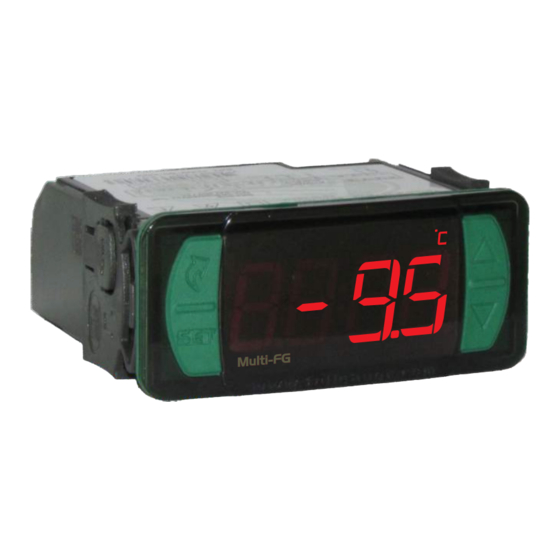
1. DESCRIPTION
Multi-FG is an interface intended for controllers with RS485 connection and compatible protocol,
and it can be used with up to 32 instruments.
It enables viewing temperatures and controller status, changing the value of function parameters, and
sending commands. The instruments to be viewed may be changed automatically or manually.
2. APPLICATIONS
Multi-FG protocol.
Interface for controllers compatible with
5. INSTALLATION - ELECTRICAL CONNECTIONS AND PANEL
Panel
(Side View)
ATTENTION
FOR INSTALLATIONS WHERE A SEALING IS REQUIRED TO
AVOID LIQUID CONTACT, THE CUT FOR THE CONTROLLER
MUST BE OF 70,5X29mm MAXIMUM. THE SIDE LOCKS MUST BE
FIXED SO IT PRESSES THE RUBBER SEALING AVOIDING
INFILTRATION BETWEEN THE CUT AND THE CONTROLLER.
6. FIRST STEPS
6.1 Electric connection and RS485 Network
After all connections are ready (sensors, relays, valve, and RS-485 networks) the configuration must be carried out with one controller at a time. To do this, power up only the first controller to be configured. When
Multi-FG
has no instruments registered in the scan list the message [None] blinks on the main screen. Follow the next steps in this chapter to add the address of the controller in
B A
Multi-FG
115/230 Vac MAINS
Multi-FG
Sitrad
VEE
Power
6.2 Entering the access code
>
Access the main menu by pressing the keys
6.3 Adding a new controller
Follow the steps below to add new network controllers:
1) With the access code previously entered (according to item 6.2), use the keys
The value to be sent to the controller in its new address is shown in the display. Adjust the value using the keys
- The message [done] is displayed if the address is successfully configured.
- The message [used] is displayed if the address is already on the list.
- The message [Ecnn] is displayed if there is an error in the connection.
NOTE: In case of connection error, check the terminals for correct connection and tightening and the wires for ruptures. Try the same command again after checking.
Multi-FG
REMOTE INTERFACE FOR
DIGITAL CONTROLLERS
Defrost
Functions
manual
lockdown
71
± 0,5
mm
Dimension of the clipping
for setting of the
instrument in panel
Panel (Front View)
IMPORTANT
THE USE OF APPROPRIATE TOOLS IS ESSENTIAL TO AVOID
DAMAGE IN THE CONNECTION AT INSTRUMENT TERMINALS:
SCREWDRIVER SLOT 3/32''(2.4mm) FOR ADJUSTMENTS IN
THE SIGNAL TERMINALS;
SCREWDRIVER PHILLIPS #1 FOR ADJUSTMENTS IN THE
POWER TERMINALS;
A
A
B
B
A B
A B
vx-
950 plus
MULTI-FG
SENS. TEMP. / DIG. IN
1 | multi-FG (A)
5-6 | digital input (door)
2 | multi-FG (B)
6-7 | sens. suction temp.
8-9 | sens. evap. temp.
SENS. PRESS.
3 |
12Vdc (brown)
9-10 | sens. ambient temp.
4 |
4~20mA (green)
SITRAD
RELAYS
11 | SITRAD (A)
13-14 | fans
12 | SITRAD (B)
15-16 | compressor
17-18 | defrost
|
Power Supply
12Vdc - 1.3A
12Vdc
1.3A
<
, simultaneously. Menu [Code]will be displayed upon releasing the keys. Enter the code 123 to gain full access to the other menus.
and
>
<
to access the menu [ADD,] and then press
or
IP 65
FRONT
Protection
level
3. TECHNICAL SPECIFICATIONS
Power supply
Control temperature
Dimensions
Dimensions of the clipping for
fixing of the instrument
4. INDICATIONS AND KEYS
Compressor output indicator led
Address switching indicator led
Quick Access
Menu Key (Flatec)
Set key
Connection 115 Vac
Connection 230 Vac
A
A
B
B
A B
A B
vx-
950 plus
MULTI-FG
SENS. TEMP. / DIG. IN
Multi-FG
1 | multi-FG (A)
5-6 | digital input (door)
Sitrad
2 | multi-FG (B)
6-7 | sens. suction temp.
8-9 | sens. evap. temp.
VEE
SENS. PRESS.
3 |
12Vdc (brown)
9-10 | sens. ambient temp.
Power
4 |
4~20mA (green)
SITRAD
RELAYS
11 | SITRAD (A)
13-14 | fans
12 | SITRAD (B)
15-16 | compressor
17-18 | defrost
|
Power Supply
12Vdc - 1.3A
12Vdc
1.3A
/
.
>
<
/
and
and press
to confirm.
M ult i-F G
M ult i-F G
Multi-FG: 115 or 230 Vac ±10%(50/60 Hz)
0 to 50°C / 32 to 122°F
76 x 34 x 77 mm (WxHxD)
71 ± 0,5 x 29 ± 0,5 mm (see item 5)
Fan indicator led
Defrost indicator led
Economy mode indicator led
Temperature unit indicator led
Multi-FG
A
B
POWER
5 6 7 8
SUPPLY
9
10 11 12 13 14 15 16 17
1
2 3 4
115 Vac
A
B
POWER
5 6 7 8
SUPPLY
9
10 11 12 13 14 15
1
2 3 4
230 Vac
Multi-FG
Full Gauge Controls recommends:
A
A
120Ω
B
B
- Use a 120 Ω termination resistor in
A B
terminals A and B of the last network
connection block.
A B
- Maximum cable length is 100 meters.
vx-
950 plus
MULTI-FG
SENS. TEMP. / DIG. IN
Multi-FG
1 | multi-FG (A)
5-6 | digital input (door)
Sitrad
2 | multi-FG (B)
6-7 | sens. suction temp.
8-9 | sens. evap. temp.
VEE
SENS. PRESS.
3 |
12Vdc (brown)
9-10 | sens. ambient temp.
Power
4 |
4~20mA (green)
SITRAD
RELAYS
11 | SITRAD (A)
13-14 | fans
12 | SITRAD (B)
15-16 | compressor
17-18 | defrost
|
Power Supply
12Vdc - 1.3A
12Vdc
1.3A
evolution
Increase key
Decrease key
16 17
.
LEGEND
Powered down controller
Advertisement
Table of Contents

Related Manuals for Full Gauge Controls EVOLUTION Multi-FG

Summary of Contents for Full Gauge Controls EVOLUTION Multi-FG
- Page 1 If you have any questions, please contact technical support. Fan indicator led Defrost indicator led DUE TO YOUR CONSTANT EVOLUTION, THE FULL GAUGE CONTROLS RESERVES THE RIGHT TO Compressor output indicator led Economy mode indicator led CHANGE THE INFORMATION CONTAINED IN THIS MANUAL AT ANY TIME WITHOUT NOTICE.
- Page 2 2)In the same menu, power up the second controller, select a new address, and then press . Repeat this operation until all controllers in the network have addresses configured. NOTE: The menu [Add,] has a 15-second time limit if no key is pressed. The message [----]is displayed after this time and returns to the temperature display. Multi-FG 115/230 Vac MAINS 950 plus...
- Page 3 Inhibits the audible alarm. [inib] Products manufactured by Full Gauge Controls, as of May 2005, have a two (02) year warranty, as of the date of the consigned sale, as stated on the invoice. They are guaranteed Multi-FG not programmed.
Need help?
Do you have a question about the EVOLUTION Multi-FG and is the answer not in the manual?
Questions and answers