
Related Manuals for Intuicom Communicator II


Summary of Contents for Intuicom Communicator II
- Page 1 Intuicom® Communicator II Spread Spectrum Wireless Data Transceiver User Guide Intuicom, Inc. 1880 S Flatiron Court Boulder, CO 80301 (303) 449-4330 www.intuicom.com...
- Page 2 Intuicom reserves the right to make changes to this manual without notice. Unless otherwise agreed to in writing, Intuicom assumes no responsibility or liability for the use of this manual or for the infringement of any copyright or other proprietary right and Intuicom shall deem nothing contained in this manual a warranty or guarantee.
- Page 3 Diversion contrary to U.S. law is prohibited. Shipment or re-export of this product outside of The United States may require authorization by the U.S. Bureau of Export Administration. Please contact Intuicom, Inc. for assistance and further information. Revision 1.0c © 2003 Intuicom Inc.
-
Page 4: Table Of Contents
Communicator II User Guide Table of Contents Product Overview ......................... 1 Communicator II roles in Intuicom Wireless Data Networks......... 1 Quick Start ..........................2 Quick Start on a Multipoint System ................... 3 0) Set Operation Mode....................3 1) Set Baud Rate......................3 3) Edit Radio Transmission Characteristics.............. - Page 5 Communicator II User Guide (B) ModBus RTU......................22 (C) RS232/485....................... 22 (D) Setup Port ....................... 23 (E) Turn on/off delay..................... 23 (F) Flow Control......................24 Call Book (Main Menu Option 2)..................25 Entering or Modifying numbers in the Call Book............26 Programming the Call Book to Use 3 or 4 Repeaters ..........
- Page 6 Communicator II User Guide 19.1 900 Mhz Band Communicator II................... 55 19.2 2.4 Ghz Band Communicator II ..................57 Enclosure Mechanical Drawing..................59 FCC Notification ......................60 Warranty ......................... 61 Revision 1.0c © 2003 Intuicom Inc.
- Page 7 Communicator II User Guide List of Tables Table 4-1: Serial Settings to access Setup Menu ................4 Table 5-1: Mode 6 Commands ....................... 9 Table 6-1: Subnet ID Settings for example Multipoint Subnet Diagram ........19 Table 7-1: Data word length and parity selections ............... 22 Table 7-2: Data port protocol selections..................
- Page 8 Communicator II User Guide Table of Figures Figure 1-1: Intuicom Communicator II Front Panel ............... 1 Figure 4-1: Setup Main Menu......................5 Figure 5-1: Operation Mode Menu ....................6 Figure 5-2: Call Book Menu ......................10 Figure 6-1: Multipoint Parameters....................15 Figure 6-2: Multipoint Subnet Diagram ..................
-
Page 9: Product Overview
Welcome to the Intuicom Communicator II License-Free Spread-Spectrum Wireless Data Transceiver. The Intuicom Communicator II can be used in a wide variety of roles to wirelessly enable the flow of data to and from serial devices. Communicator II transceivers can be operated... -
Page 10: Quick Start
The transceivers function as a 9-pin null modem cable. If the Communicator II is to be used in an application where a null modem cable is used (such as communication between two computers), then the transceivers can be connected directly. If the transceivers are to be used to replace a straight-through RS232 cable, then a null modem cable or adapter must be placed between the transceiver and the DCE instrument to which it is connected. -
Page 11: Quick Start On A Multipoint System
Will there be a repeater in the network or do you intend to be able to run diagnostics on the network? If so set that value to 1. Set the NetworkID to a value between 1 and 4095, a value of 255 enables the use of the callbook. The rest is just fine-tuning. Revision 1.0c © 2003 Intuicom, Inc. -
Page 12: Tuning Transceiver Performance
Table 4-1: Serial Settings to access Setup Menu When the setup program is invoked all three LEDs on the Communicator II front panel will turn green and will remain green for the entire time the transceiver is in setup mode. The main menu screen for the setup program is shown in Figure 4-1: Revision 1.0c... -
Page 13: Figure 4-1: Setup Main Menu
Section 4: Tuning Transceiver Performance Figure 4-1: Setup Main Menu The initial menu provides the transceiver's unique serial number, firmware version, and the set of choices for editing the operational parameters and viewing the performance data. Revision 1.0c © 2003 Intuicom, Inc. -
Page 14: Operation Mode Selections (Main Menu Option 0)
Operation Mode option is used to designate the method in which the particular transceiver will be used. The Communicator II operates in a Master to Slave configuration; therefore, any transceivers that are intended to operate together must be set up as such. In a point-to-point setup, either the master or slave may be used on either end of the communications link without any performance degradation. -
Page 15: 1) Point-To-Point Slave
LEDs will be solid red. (1) Point-to-Point Slave When set up as a point to point slave a Communicator II transceiver will communicate with any master in its call book, either directly or through up to four repeaters. When functioning as a slave, the Entry to Call feature in the transceiver's call book Figure 5-2 is not operational. -
Page 16: 5) Point-To-Point Repeater
This, in turn, allows the user to establish push button command sets that will instruct the Transceiver to call a predetermined slave. Note: All AT commands issued to the transceiver in Mode 6 must be in ALL CAPS Revision 1.0c © 2003 Intuicom, Inc. -
Page 17: Table 5-1: Mode 6 Commands
ATXP_ RF Transmit Power ATDT_ Position in Call Book to Call ATD_ Allows specific Intuicom Communicator II serial number to be entered to call ATXC_ Used in conjunction with the ATD command, instructs transceivers which repeater path to follow ATXS... -
Page 18: Figure 5-2: Call Book Menu
The Slave security may be disabled so that a modem operating as a slave (Modes 1,4, and 6) will connect to any modem calling it regardless of whether the calling modem is in the slave’s Call Book. This feature is necessary when there are more than 10 transceivers which Revision 1.0c © 2003 Intuicom, Inc. -
Page 19: 7) Point-To-Multipoint Repeater
Please refer to the next chapter, 'Multipoint Operation', for more information on running a Multipoint network. TDMA (If TDMA firmware option installed) Please contact Intuicom for more information about the TDMA operation mode firmware option. 5.10 (F) Ethernet options This menu is only needed for Ethernet modems. Although this menu is included here, it has nothing to do with the Modem Mode (for example, if the modem mode is "0", entering "F"... -
Page 20: Multipoint Operation
Unlike point-to-point systems (where the master will set certain system parameters), a multipoint system requires that many parameters be set consistently on all transceivers in the system. This includes RF data rate, min and max packet size, number of repeaters, and frequency key. Revision 1.0c © 2003 Intuicom, Inc. -
Page 21: Overlapping Multipoint Systems
In this scenario it becomes very important to include as much frequency and time diversity as possible through use of different frequency keys, min and max packet sizes, and frequency banks. Please contact Intuicom if you have any questions about the installation of multipoint systems. -
Page 22: Master Packet Repeat In Multipoint Systems With Repeaters
The data communications between the master and those slaves communicating through the repeater will be marginal, because it is only as strong as the weakest link, which in this case is the link between the repeater and slaves. Revision 1.0c © 2003 Intuicom, Inc. -
Page 23: 2) Max Slave Retry And (3) Retry Odds
RF link and the other far from the master with a weak link. It may be desirable to assign a higher Retry Odd to the slave with the weaker link to give it a better chance of competing with the closer slave for the master's attention. Revision 1.0c © 2003 Intuicom, Inc. -
Page 24: 4) Dtr Connect
The repeater may be programmed to either use the master's hopping pattern (selection 0) or its own (selection 1). Please contact Intuicom for more information regarding Repeater Frequency. 6.4.7 (6) NetWork ID Option (6) NetWork ID allows multipoint networks to be established without the use of the Call Book. -
Page 25: A) Slave/Repeater
Proper use of diagnostics requires the following: 1. Diagnostics must be enabled on the Master (set to 1) 2. A second serial port (or computer) to run the diagnostics software Revision 1.0c © 2003 Intuicom, Inc. -
Page 26: C) Subnet Id
Section 6: Multipoint Operation 3. Diagnostics software, available through Intuicom. Please contact Intuicom if you are interested in using the diagnostics feature in your network. 6.4.12 (C) Subnet ID In a Multipoint Network where the Network ID is used (instead of the Call Book) when a slave is initially powered it will connect with the first Repeater or Master that it hears with the same Network ID. -
Page 27: Table 6-1: Subnet Id Settings For Example Multipoint Subnet Diagram
If you set both Subnet IDs to 'FF', the modem will communicate with any other modem in the same sub-network. Other than that, you can set any value for these settings. Revision 1.0c © 2003 Intuicom, Inc. -
Page 28: D) Radio Id
Section 6: Multipoint Operation 6.4.13 (D) Radio ID Option (D) allows a transceiver to be designated with an arbitrary, user selectable, 4 digit number which identifies the transceiver in the diagnostics mode. Revision 1.0c © 2003 Intuicom, Inc. -
Page 29: Baud Rate (Main Menu Option 1)
Transceiver(s) in the communication loop. For example, a Communicator II may be used in an application to send data from remote process instrumentation to an engineer's computer. In this application the baud rate for the Transceiver on the instrumentation might be set to 9600, and the Transceiver on the computer might be set to 57,600 or 115,200. -
Page 30: A) Data Word Length And Parity
Section 7: Baud Rate (Main Menu Option 1) (A) Data Word Length and Parity There are six data word length and parity configurations available to be used with Intuicom Communicator II transceivers. The default setting is 0 (8,N,1) and is the most commonly used serial communications protocol. -
Page 31: D) Setup Port
RS485 bus, when the modem stops driving the bus and releases the bus to other devices on it. The units are ¼ of a character (so, an entry of 4 means a delay equivalent to the duration of a full character). Default is zero delay. Revision 1.0c © 2003 Intuicom, Inc. -
Page 32: F) Flow Control
Table 7-4:Flow control selections Default is 0 (no hardware flow control). Note: Flow control is in effect while interacting with the setup menu. Be sure to match the configured flow control when accessing the setup menu. Revision 1.0c © 2003 Intuicom, Inc. -
Page 33: Call Book (Main Menu Option 2)
Section 8: Call Book (Main Menu Option 2) 8 Call Book (Main Menu Option 2) The Call Book is an innovative feature in the Communicator II which offers both security and flexibility in use. The Call Book accomplishes this by allowing the user to determine with which other transceivers a given transceiver will communicate, based on the serial numbers for both the master and slave. -
Page 34: Entering Or Modifying Numbers In The Call Book
Programming the Call Book to Use 3 or 4 Repeaters In a point-to-point link the Communicator II can utilize up to 4 repeaters. To use 3 or 4 repeaters program the Call Book with the slave being called, followed by the first 2 repeaters being used (from the master calling out to the slave). -
Page 35: Figure 8-2: Calling A Slave Through 4 Repeaters
000-0000. If a valid serial number is entered after the all zero number it will not be recognized as a valid number to call by the master. Figure 8-2: Calling a Slave Through 4 Repeaters Revision 1.0c © 2003 Intuicom, Inc. -
Page 36: Programming The Call Book In Multipoint Systems
Call Book should contain only the serial number for the repeater in the upper left hand corner. Note: If the network ID option is used no entries are needed in the Call Book of any of the transceivers in a multipoint system. Revision 1.0c © 2003 Intuicom, Inc. -
Page 37: Radio Parameters (Main Menu Option 3)
Selection (0) in the Radio Parameters menu allows the user to modify the hopping patterns of the transceivers to minimize the interference with other Communicator II transceivers in operation in the area. For instance, if there were 10 pairs of transceivers in operation within a factory or refinery, changing the Frequency Key would ensure that they would not jump onto the same frequencies at the same time for the same length of time. -
Page 38: Figure 9-2: Hop Table Parameters
There are 15 choices available for the Frequency Key (0-9 and A-E), representing 15 different pseudo-random patterns. A selection of ‘F’ provides additional options to use different portions of the 902-928 MHz band. Figure 9-2: Hop Table Parameters Revision 1.0c © 2003 Intuicom, Inc. -
Page 39: 0) Hop Table Version
9.2.3 Additional Frequency information for 2.4GHz transceivers The Frequency Key for the 2.4GHz Communicator II transceivers offers the ability to select more than just a different pseudo random hop table, but also the portion of the band that the transceiver will use. Because this feature offers the ability to select which portion of the spectrum will be used it is critical that all radios in a link, whether point-to- point or point to multipoint, use the same selections. -
Page 40: Table 9-2: Frequency Band Selection 2.4 Ghz
50 frequencies, with one set to Frequency Offset of 0 and the other to Frequency Offset of 1, the frequencies used in the different hopping patterns will be offset by 115.2 Revision 1.0c © 2003 Intuicom, Inc. -
Page 41: 1,2) Max Packet Size And Min Packet Size
Selections (1) and (2) allow the user to designate the size of the packets (in bytes) used by the transceiver in its communication link. This may be of particular value when using the Communicator II with different communications software packages; you may find that throughput is optimized when packet sizes are restricted by the transceiver. It should be noted, however, that in Point to Point modes the Max and Min Packet Settings will not have any material impact on throughput unless 115.2 KBaud is desired. -
Page 42: Table 9-3: Min Packet Size Settings (Bytes)
Min Packet Size Setting RF Data Rate = 2 Setting RF Data Rate = 3 Table 9-3: Min Packet Size Settings (Bytes) Max Setting Setting Table 9-4: Max Packet Size Settings (Bytes) RF Data Rate 2 Revision 1.0c © 2003 Intuicom, Inc. -
Page 43: 3) Xmit Rate
(4) RF Data Rate The Communicator II has two settings for the RF Data Rate (not to be confused with the RS232 Baud Rate). Setting 2 should be used when the transceivers are close together and data throughput is to be optimized. Setting 2 must also be used when full throughput of 115.2 KBaud is necessary. -
Page 44: 6) Slave Security
With option 6 the user may disable the transceiver’s security so it will accept a call from any other Intuicom unit. The default setting is 0 where security is enforced (the caller’s serial number must be in the slave’s Call Book), with a setting of 1 security is disabled. -
Page 45: 8) Retry Time Out
4) To communicate to the RS232 port of a transceiver that is in Lowpower Mode the RTS line must be held high to wake it up. The transceiver will wake up within approximately 20 milliseconds or when CTS goes high. Revision 1.0c © 2003 Intuicom, Inc. -
Page 46: A) High Noise
Use this menu to set the speed of the processor (Micro Controller Unit) in the Modem. The default setting is 0 (low speed). Setting Description Notes Low Speed Reduces current consumption High Speed Required for 230 Kbaud Data Port rate Table 9-7: MCU Speed Settings Revision 1.0c © 2003 Intuicom, Inc. -
Page 47: Radio Statistics (Main Menu Option 4)
The frequency table is accessed by pressing the ENTER key on the computer when the radio statistics menu is displayed. Revision 1.0c © 2003 Intuicom, Inc. -
Page 48: Average Signal Level
Low Average Signal Levels can often be corrected with higher gain antennas, antenna placement, and use of repeaters or use of antenna amplifiers. Contact Intuicom for more information. Note, later revisions of the firmware show the signal level in RSSI units. -
Page 49: Radio Temperature
Section 10: Radio Statistics (Main Menu Option 4) 10.5 Radio Temperature The radio temperature value is the current operating temperature of the radio in degrees C (Celsius.) For proper operation, Intuicom Communicator II radio modems must be in the range of –40° to 75°C. Revision 1.0c... -
Page 50: Tdma Menu (Main Menu Option 6)
11 TDMA Menu (Main Menu Option 6) Access to the TDMA operating mode and operating parameters requires TDMA enabled firmware. Please contact Intuicom for information about TDMA firmware. The TDMA configuration parameters are covered in a separate manual: Designing and Configuring TDMA Networks. -
Page 51: Password (Main Menu Option 8)
CAUTION: If the password feature is enabled and you cannot remember the password the radio will need to be sent back to Intuicom to have the password disabled. Option (8) in the Main Menu allows the user to set a password that will prevent access to changing of any of the radio’s parameters. -
Page 52: Transceiver Location
Section 13: Transceiver Location 13 Transceiver Location Placement of your Intuicom Communicator II unit is likely to have a significant impact on its performance. In general the rule of thumb with a Communicator II is that the higher the placement of the antenna the better the communication link - height is everything! In practice you should also place the transceiver away from computers, telephones, answering machines, and other similar equipment. -
Page 53: Front Panel Leds
Section 14: Front Panel LEDs 14 Front Panel LEDs The LEDs on a Communicator II's front panel provide important information on the operation of the transceiver. Compare the status of a Transceiver's LEDs with the table below to aid you in the troubleshooting process. -
Page 54: Rs232 Pin Assignments
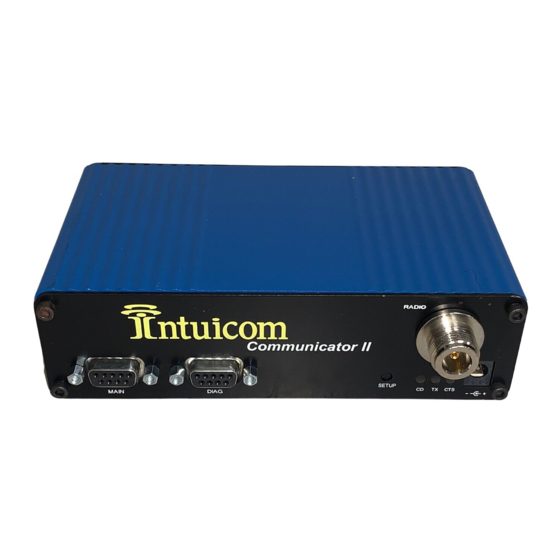
Section 15: RS232 Pin Assignments 15 RS232 Pin Assignments RADIO ommunicator SETUP TX CTS MAIN DIAG Figure 15-1: Communicator II Front Panel Assignment Signal Carrier Detect Output Transmit Data Output Receive Data Input Input Ground (Signal/Power) +Vin Input/Output Input Clear to Send... -
Page 55: Table 15-3: Signal Definitions
This should always be used for data rates above 38.4KB or there will be a risk of lost data if an RF link is not very robust. Pin 9: N/C Table 15-3: Main Port Signal Definitions Revision 1.0c © 2003 Intuicom, Inc. -
Page 56: Establishing Data Communication Links
Section 16: Establishing Data Communication Links 16 Establishing Data Communication Links The Communicator II’s versatility allows data communication links to be established using a variety of different configurations. This, in turn, makes it possible to extend the range of the Communicator II and get around obstacles. -
Page 57: Figure 16-3: Point-To-Point With Two Repeaters
At any time desirable the master may call any of the slaves, establish a connection, and retrieve and send data. Master Slave Slave / Slave Repeater Slave Repeater Figure 16-4: Point-to-Point with Slave/Repeaters Revision 1.0c © 2003 Intuicom, Inc. -
Page 58: Figure 16-5: Point-To-Multipoint Network
This system works in a manner very similar to a standard multipoint system with repeaters, however the number of radios needed is reduced with the use of the multipoint slave/repeater feature. Revision 1.0c © 2003 Intuicom, Inc. -
Page 59: Figure 16-6: Point-To-Multipoint With Repeaters
Section 16: Establishing Data Communication Links Master Slave Slave Multipoint Slave/Repeater Slave Slave Multipoint Repeater Figure 16-6: Point-to-Multipoint with Repeaters Revision 1.0c © 2003 Intuicom, Inc. -
Page 60: Rs422 And Rs485 Operation
There is no provision for hand shaking in any of the above modes of operation so fast data rates (57.6 K baud and above) are not recommended without a protocol that can handle error detection properly. Revision 1.0c © 2003 Intuicom, Inc. -
Page 61: Table 17-1: Rs422 And Rs485 Full Duplex Pinouts
Function DE-9 Pin Number Wire to both pins for Buss + Short 2 & 3 Wire to both pins for Buss - Short 7 & 8 Table 17-2: Main Port RS485 Half Duplex Pinout Revision 1.0c © 2003 Intuicom, Inc. -
Page 62: Other Settings
Section 18: Other Settings 18 Other Settings A number of parameters other those shown in the setup menu may be set on Intuicom Communicator II transceivers. The parameters below may be set with DOS based software available by contacting Intuicom. -
Page 63: Technical Specifications
Section 19: Technical Specifications 19 Technical Specifications 19.1 900 Mhz Band Communicator II Specification Value Frequency: 902 to 928 MHz Transmitter: 1 mW to 1 W (+30 dDm) Output Power Range* 60 miles Modulation Spread Spectrum GFSK, 120 kBs – 170 kBs... - Page 64 Power Requirements • AC Wall Adapter Provided • May also be powered through Pin 9 of Diag DB9 connector Antenna N type female connector. External antenna required. FCC Identifier KNY21161341911919 DOC Identifier 2329 102 336A Revision 1.0c © 2003 Intuicom, Inc.
-
Page 65: Ghz Band Communicator Ii
Section 19: Technical Specifications 19.2 2.4 Ghz Band Communicator II Specification Value Frequency: 2.400 to 2.4835 GHz Transmitter: Output Power 100 mW to 500 mW Range* 20 miles Modulation GFSK, 115.2 Kbps or 153.6 Kbps Occupied Bandwidth 230 kHz Receiver:... - Page 66 • 9.5 – 30 Vdc • AC Wall Adapter Provided • May also be powered through Pin 9 of Diag DB9 connector Antenna N type female connector. External antenna required. FCC Identifier KNY21161341911919 DOC Identifier 2329 102 336A Revision 1.0c © 2003 Intuicom, Inc.
-
Page 67: Enclosure Mechanical Drawing
Section 20: Enclosure Mechanical Drawing 20 Enclosure Mechanical Drawing Revision 1.0c © 2003 Intuicom, Inc. -
Page 68: Fcc Notification
This device must be operated as supplied by Intuicom, Inc. Any changes or modifications made to the device without the express written approval of Intuicom, Inc. may void the user's authority to operate the device. -
Page 69: Warranty
Hardware, and functional failure, improper operation, failure to operate according to specifications or any other matter related to the Hardware. INTUICOM shall not be liable or responsible for the failure of the Manufacturer to perform under or honor any warranty with respect to the Hardware.
Need help?
Do you have a question about the Communicator II and is the answer not in the manual?
Questions and answers