Table of Contents
Advertisement
Quick Links
P O W E R I N G
T E C H N O L O G Y
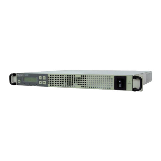
SLI15 INVERTERS
Installation & Operating Manual
www.unipowerco.com
© 2018 UNIPOWER LLC
Document Number: SLI-15-5
All Rights Reserved
sli15-man-rev5-0718.indd
UNIPOWER LLC • 3900 Coral Ridge Drive, Coral Springs, Florida 33065, USA • sales@unipowerco.com
North America: +1 954-346-2442 • Europe: +44 1903 768200
Advertisement
Table of Contents

Related Manuals for Unipower SLI15


Summary of Contents for Unipower SLI15
- Page 1 SLI15 INVERTERS Installation & Operating Manual www.unipowerco.com © 2018 UNIPOWER LLC Document Number: SLI-15-5 All Rights Reserved sli15-man-rev5-0718.indd UNIPOWER LLC • 3900 Coral Ridge Drive, Coral Springs, Florida 33065, USA • sales@unipowerco.com North America: +1 954-346-2442 • Europe: +44 1903 768200...
- Page 2 UNIPOWER LLC, which consent may be withheld by UNIPOWER LLC in its sole discretion. Users assume all risk and liability for, and agree to indemnify and defend UNIPOWER from and against any claims for personal injury (including death) or property damage resulting from any such use or application which is made in the absence of such prior express written consent.
-
Page 3: Table Of Contents
Appendix B Manual Bypass .....................44 Appendix C Grounding Restrictions Summary ..............46 Appendix D The SERVICE menu ....................47 Appendix E Default Factory Settings ..................49 Appendix F Error State Behavior ....................50 Appendix G SLI15 to ACX Translator ..................51 Page 3 Manual No. sli-15-5 sli15-man-rev5-0718.indd... - Page 4 Table A-2 Input Wire Size ..........................43 Table C-1 Grounding Restrictions .......................46 Table E-1 Factory Settings ...........................49 Table F-1 SLI to ACX Translator Signal Connections ................51 Table F-2 SLI to ACX Translator Power Connections ................52 Page 4 Manual No. sli-15-5 sli15-man-rev5-0718.indd...
-
Page 5: Chapter 1 General Information
T E C H N O L O G Y 1.1 General The SLI15 inverter is designed to operate from a DC Source, its input current features a very low ripple. Its psophometric value is 31dBnrc (without battery). The above feature allows the inverter to be supplied by a charger or power supply even without a battery in the circuit, as long as the DC source has the necessary current capacity to sustain the inverter’s inrush... -
Page 6: Feedback & Support
1.2 Feedback & Support For technical support or feedback, please visit https://www.unipowerco.com/contact/. 1.3 Disclaimer UNIPOWER is not responsible for system problems that are the result of installation or modification of the instructions provided in this manual. Page 6 Manual No. sli-15-5... -
Page 7: Chapter 2 Location Selection
P O W E R I N G T E C H N O L O G Y The SLI15 Inverter is designed for indoor applications, away from heat and moisture. The inverter will provide its full performance with internal forced ventilation at ambient temperatures ranging from -25°C to +55°C (+65°C with power derating, see also Technical Specifications). -
Page 8: Chapter 3 Instructions
NOTE For your protection, the following information and the rest of this manual should be read and thoroughly understood before unpacking, installing or using the equipment. All UNIPOWER products are handed over to the delivering carrier securely packed and in perfect condition. Upon acceptance of the package from us, the delivering carrier assumes responsibility for its safe arrival to you. -
Page 9: Identification Label
3.4 Identification Label The model number and serial number located on the label on the cover identify the unit. Please refer to these numbers in all correspondence with UNIPOWER. 3.5 Initial Settings All inverters are shipped from our production facility fully checked and adjusted. Do not make any adjustments until you have read this manual. -
Page 10: Chapter 4 Mounting Procedure
4 x screws to connect the handles to the brackets (2 + 2). Flush Mount Bracket Holes Center Mount Bracket Holes Figure 4-1 Fitting Mounting Brackets 1.25” 1.75” 31.7mm 44.45mm Page 10 Manual No. sli-15-5 sli15-man-rev5-0718.indd 18.3” | 465.1mm 19” | 485mm... -
Page 11: Connections
NOTE Consult Appendix “A” to set the proper wire size, length and terminal types for the 24V or 48V inverters models vs. distance from the source. (11) Page 11 Manual No. sli-15-5 sli15-man-rev5-0718.indd 18.3 (465.1) [19” mounting centres] 19.1 (485) -
Page 12: Figure 4-5 Dc Input Clips In Sub-Rack
T E C H N O L O G Y 4.2.1.1 Inserting a Hot-Plug Inverter Module Into The Sub-Rack Before inserting the SLI15 inverter module into the sub-rack coat the inner DC input clips with conducting paste for better electrical conduction and easier manipulation during insertion, see Figure 4-5. -
Page 13: Figure 4-8 Ac Output Connections For N-Inverters In Parallel Configuration - Plug Connectors
(models with plug connectors - Note: L1=1; L2=2 ; PE=3) AC Outlet UNIT 1 LOAD AC Outlet UNI T “n” Figure 4-9 AC Output Connections for n-inverters in parallel configuration (models with screw terminals) Page 13 Manual No. sli-15-5 sli15-man-rev5-0718.indd... -
Page 14: Figure 4-10 Ac Grid Input Connections For Parallel Configuration - Plug Connectors
GRID AC Grid Inlet On UNI T 1 Length A = Length B GRID AC Grid Inlet On UNI T “n” Figure 4-11 AC grid input connections for parallel configuration (models with screw terminals) Page 14 Manual No. sli-15-5 sli15-man-rev5-0718.indd... -
Page 15: Figure 4-12 Signal Connector Type
For parallel mode only. Sync-240 Dedicated to the synchronization of units Y connected for 3-phase voltage generation. Sync For parallel mode only. +TR/I (Reserved) Reserved (do not connect to this pin). Table 4-1 Signal Description Page 15 Manual No. sli-15-5 sli15-man-rev5-0718.indd... -
Page 16: Figure 4-13 Parallel Configuration Signal Connections
T E C H N O L O G Y 4.2.3.1 Connecting units in parallel using the 15-pole connector To operate two or more (max. 6) SLI15 inverters in parallel, pins 5, 6, 12, 14 of each unit must be connected together as shown in Figure 4-13. -
Page 17: Figure 4-14 Parallel Adapter For Standalone Units
Figure 4-14 Parallel Adapter for Standalone Units UNIPOWER provides a paralleling adapter kit which consists of one board assembly and one link cable/ferrite assembly. One kit is required for plugging into each inverter in a paralleled set. The part number for ordering this kit is 3C35000KIT7G, see the data sheet. -
Page 18: Figure 4-15 Parallel Adapter For Hot-Plug Units
Figure 4-15 Parallel Adapter for Hot-Plug Units One link cable/ferrite assembly, order part number 3C3500KITHPG, will be required for for connecting between each shelve, e.g. for 3 units in parallel two are required. Page 18 Manual No. sli-15-5 sli15-man-rev5-0718.indd... -
Page 19: Figure 4-16 Signal Connections For 3-Phase Y Output Configuration
Inverter #3a Chassis ground (pin 6) Figure 4-16 Signal Connections for 3-phase Y Output Configuration NOTE 3 paralleled pairs of SLI15 inverters may also be configured in this way to provide a total of 3000W per output phase. Page 19 Manual No. -
Page 20: Step By Step Procedure To Turn On The Unit
4.3.2 Models without the optional Static Transfer Switch, in parallel configuration 4.3.2.1 Setting up the units Make sure every AC load is disconnected and the AC Output Breaker on front panel of each inverter is turned OFF. Page 20 Manual No. sli-15-5 sli15-man-rev5-0718.indd... - Page 21 Re-cycle the DC input voltage. After this is done the Inverter is set to work in parallel configuration. Connect the Signal connector to the unit. Refer to paragraph 4.2.3. Connect the grid. Refer to paragraph 4.2.2.4. Page 21 Manual No. sli-15-5 sli15-man-rev5-0718.indd...
- Page 22 Press “Enter” to indicate the frequency. • Return the unit to stand-by, pressing the “ON/OFF” key. If it is necessary change the Vout and/or Frequency values, please follow the procedure in the next step. Page 22 Manual No. sli-15-5 sli15-man-rev5-0718.indd...
- Page 23 2. Connect the load to the inverter as described in paragraph 4.2.2. 3. Press the ON/OFF key to turn the unit ON 4. Switch the front panel AC Output Breaker ON. The unit should be feeding the load. Page 23 Manual No. sli-15-5 sli15-man-rev5-0718.indd...
- Page 24 In order to allow the grounding of the neutral an isolation transformer has to be used between the inverters’ output and the load. Ask your UNIPOWER technical or commercial interface about suggestions on how to do it.
- Page 25 Static Transfer Switch is normally switched on the inverter. • Mode 2 = “Off-Line Mode”. The grid is the primary source and the Static Transfer Switch is normally switched on the grid. Page 25 Manual No. sli-15-5 sli15-man-rev5-0718.indd...
- Page 26 Connect the load to the inverter as described in paragraph 4.2.2. Press the ON/OFF key to turn the unit ON. Switch the front panel AC Output Breaker ON. The unit should now be feeding the load. Page 26 Manual No. sli-15-5 sli15-man-rev5-0718.indd...
-
Page 27: Chapter 5 "User Guide
Speed of one of the fans is below its nominal value. FAULT (red) More than one fan has stopped or a general malfunction is detected. FAN FAIL (red) The unit continues to works until an O.T. is detected. Page 27 Manual No. sli-15-5 sli15-man-rev5-0718.indd... -
Page 28: Startup Sequence And The Standby Status
(Vout/Iout, Vout/Freq, Iout/Pout,…). When pressing <ENTER> the screen (1) is viewed for a short time, then the display goes back to the previous screen automatically. By pressing <ESC> the SETTINGS menu is displayed. Page 28 Manual No. sli-15-5 sli15-man-rev5-0718.indd... -
Page 29: Operating Modes
When the unit works in Parallel mode it is not possible to change the following parameters in the SETTINGS menu: Vout, Iout, Frequency. Access to these parameters is locked to avoid system conflicts (see also Notes on page 36). Page 29 Manual No. sli-15-5 sli15-man-rev5-0718.indd... -
Page 30: Controller Status
UTILITY submenu To view the unit configuration (Stand-Alone, Parallel Mode, Master,…) STATUS menu To get info about the unit's Part Number, Serial Number and Firmware INFO menu revision number. Figure 5-3 Main Menu Structure Page 30 Manual No. sli-15-5 sli15-man-rev5-0718.indd... -
Page 31: The Settings Menu
Figure 5-2 and also Appendix D). • Change the Led Status (ON/OFF). • Set the Buzzer (ON/OFF). • Set the Fans (ON/OFF) and the Fan Speed. • Read fan Speed, System Temperature, Internal Temperature and Ambient Temperature. Page 31 Manual No. sli-15-5 sli15-man-rev5-0718.indd... -
Page 32: Figure 5-4 Settings Menu Navigation
Example: SETTINGS Menu - - > level submenu "……" - - > level submenu "……" - - > 1.1.1 "……" - - > 1.1.2 "……" - - > Figure 5-4 Settings Menu Navigation Page 32 Manual No. sli-15-5 sli15-man-rev5-0718.indd... -
Page 33: Figure 5-5 Settings Menu Structure
Wait Time xx Sec Figure 5-5 Settings Menu Structure For the Protections operating procedure, please see section 5.6.5 on page 37. For the Tranfer Switch operating procedure, please see section 5.6.6 on page 38. Page 33 Manual No. sli-15-5 sli15-man-rev5-0718.indd... - Page 34 - The back light time lenght can be set from 2 to 60 sec. - To enable the audible "click" when a key is pressed - Factory setting: 20sec. - Factory setting: "Click ON" Page 34 Manual No. sli-15-5 sli15-man-rev5-0718.indd...
- Page 35 3. 3.After the changes are done restore the parallel mode with the same procedure described in step 1. It is strongly recommended to set all units with identical Vout, ILIMIT, Frequency and Remote ON/OFF values when working in parallel. Page 35 Manual No. sli-15-5 sli15-man-rev5-0718.indd...
-
Page 36: Figure 5-6 Protections Sub-Menu Structure
For any protection it is possible to set the wait time between two restart attempts. The wait time has to be defined in the following range: 2 sec - 60sec max. Factory setting = 5 sec. Page 36 Manual No. sli-15-5 sli15-man-rev5-0718.indd... -
Page 37: Figure 5-7 Transfer Switch Sub-Menu Structure
Vout lies beyond the voltage mask limits, the STS switches the load to the grid (which is the Not Connected secondary or back-up source in this case). The check of Vout is made on its peak value. 1.12.6.2 Connected to the inverter 1.12.6.3 Page 37 Manual No. sli-15-5 sli15-man-rev5-0718.indd... -
Page 38: Figure 5-8 Sts Voltage Mask
If the frequency is set to 50Hz in the SETTINGS menu and the Frequency tolerance is set at 1.12.6.1 1.12.6 3%, then the STS changes state only if the frequency of the primary source exceeds 51.5Hz Not Connected or falls below 48.5 Hz. 1.12.6.2 Connected to the inverter 1.12.6.3 Page 38 Manual No. sli-15-5 sli15-man-rev5-0718.indd... - Page 39 Not Connected 1.12.6.2 Connected to the inverter 1.12.6.3 With this setting it is possible to force the STS to connect the load to the grid, to the inverter ,or to maintain the load disconnected. Page 39 Manual No. sli-15-5 sli15-man-rev5-0718.indd...
-
Page 40: Figure 5-9 Status Menu
Parallel (or Stand - Alone) INFO Menu Figure 5-9 STATUS Menu The STATUS menu shows: • the current status (Master or Slave). • the current configuration mode (Stand Alone mode or Parallel mode). • the serial port address. Page 40 Manual No. sli-15-5 sli15-man-rev5-0718.indd... -
Page 41: Figure 5-10 Info Menu
Serial Number: factory serial number, including manufacturing week & year. • Firmware revision: DSP Software release for the DC-DC stage. DSP Software release for the DC-AC stage. DSP Software release for the Controller stage. Page 41 Manual No. sli-15-5 sli15-man-rev5-0718.indd... - Page 42 P O W E R I N G T E C H N O L O G Y Page 42 Manual No. sli-15-5 sli15-man-rev5-0718.indd...
-
Page 43: Appendix A Input Power Requirements And Dc Input Wire Sizing
324082 5 AWG 324047 3 AWG 2 AWG 324053 330966 SLI-24-XXX 2 AWG 324053 2 x 2 AWG 324053 2 x 1 AWG 324053 2 x 0 AWG 55822-1 Table A-2 Input Wire Size Page 43 Manual No. sli-15-5 sli15-man-rev5-0718.indd... -
Page 44: Appendix B Manual Bypass
Manual Bypass to keep the load powered. • disconnect by the relative MCB the AC input to the inverter. • disconnect by the relative MCB the DC input to the inverter. Page 44 Manual No. sli-15-5 sli15-man-rev5-0718.indd... - Page 45 MCB the AC input to the inverter. • press ON/OFF button to turn the inverter on. • move the rotator switch to the position Normal. WARNING Different sequencing from the above may result in severe damage of the unit. Page 45 Manual No. sli-15-5 sli15-man-rev5-0718.indd...
-
Page 46: Appendix C Grounding Restrictions Summary
Utility Grid Grid IN INVERTER 1 LOAD Inv. OUT External Grounding of Neutral Grid IN INVERTER 2 Inv. OUT Grid IN INVERTER n Inv. OUT Figure C-1 Grounding of Neutral for Inverters with Transfer Switch Page 46 Manual No. sli-15-5 sli15-man-rev5-0718.indd... -
Page 47: Appendix D The Service Menu
2. Change the 2 level Password Define a new password for the “SERVICE” Menu. The password length is 4 digits. Use the <UP> and <DOWN> keys to type the characters on the display. Press <ENTER> to confirm. Page 47 Manual No. sli-15-5 sli15-man-rev5-0718.indd... - Page 48 The Wait Time is the time between two restart attempts (only for the “Restart xx times” mode). The Wait Time can be defined in the following range: 2sec to 60sec. Factory setting = 5 sec. Page 48 Manual No. sli-15-5 sli15-man-rev5-0718.indd...
-
Page 49: Appendix E Default Factory Settings
“On-Line “ = “Mode 1” SERVICE MENU (Sub-Menu of SETTINGS MENU) Password 1111 Operat. Mode “Stand-alone” = “Mode 0” System Time-out Mode Auto-restart Restart Attempts 5 times Wait Time (between 2 attempts) 5 sec. Table E-1 Factory Settings Page 49 Manual No. sli-15-5 sli15-man-rev5-0718.indd... -
Page 50: Appendix F Error State Behavior
29 - Inverter Communication ERROR Auto Restart or Latch OFF * 30 - Internal ERROR V_SENSE FAIL (read output voltage DSP Auto Restart or Latch OFF * Inverter Failed ) * Mode can be programmed by user. Page 50 Manual No. sli-15-5 sli15-man-rev5-0718.indd... -
Page 51: Appendix G Sli15 To Acx Translator
1. Install the inverters as described in the main body of this manual. 2. Install the SLI15 to Guardian Translator to the DIN rail at the rear of the distribution module of the Guardian system. See the appropriate Guardian System Manual for details of how to access the relevant area. -
Page 52: Table F-2 Sli To Acx Translator Power Connections
1. Install the inverters as described in the main body of this manual. 2. Install the SLI15 to Guardian Translator to a suitable DIN rail which should be mounted on the relay rack or cabinet as close to the DC power system as is practical. -
Page 53: Figure F-2 Typical System Schematic
Figure F-2 Typical System Schematic This document is believed to be correct at time of publication and UNIPOWER LLC accepts no responsibility for consequences from printing errors or inaccuracies. Specifications are subject to change without notice. Page 53 Manual No.
Need help?
Do you have a question about the SLI15 and is the answer not in the manual?
Questions and answers