
Related Manuals for MDS Power IPSi2400X


Summary of Contents for MDS Power IPSi2400X
- Page 1 INSTALLATION & OPERATION MANUAL IPSi2400X STEEL MILL INVERTER T. T.514.369.4919 TF. 800.931.49 www.mdspower.com...
-
Page 3: General Precautions
INVERTER IMPORTANT SAFETY INSTRUCTIONS SAVE THESE INSTRUCTIONS — This manual contains important safety and operating instructions for the Inverter. GENERAL PRECAUTIONS Do not expose the Inverter to rain or snow. Use of an attachment not recommended or sold by the Inverter manufacturer may result in a risk of fire, electric shock, or injury to persons. - Page 4 TABLE OF CONTENTS • Front Cover • Product Warnings and Advisories • Table of Contents • Introduction • Box Contents • Main Parts • Operation • Installation • Options • Troubleshooting • Specifications • Warranty...
-
Page 5: Box Contents
Introduction The IPSi1205/2405 series High Voltage Inverters are designed specifically for powering on- board computers and sensitive AC loads from high voltage (205-390 VDC) DC power sources. The transformer-based design also allows us to provide double the rated power for a few seconds which means that we can start up electric motors, shop vacuums, air conditioners and other difficult AC loads. -
Page 6: Main Parts
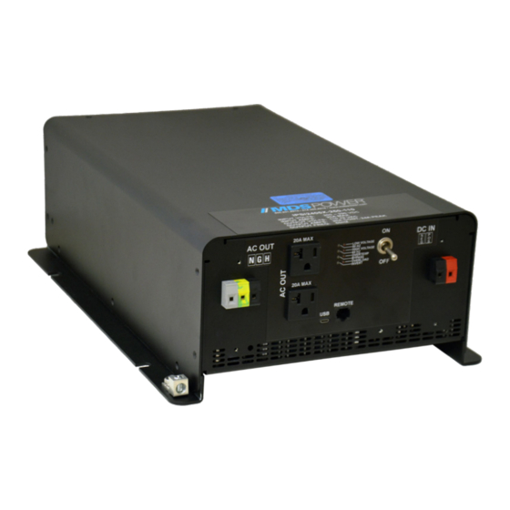
Main Parts Front Panel AC Output Connection 1: 2x Chassis Grounding Stud NEMA 5-20 AC receptacle 739W- Indicator LEDs X2/20 Power Switch AC Output Connection 2: 3x DC Input Connection: 2x Phoenix Phoenix VDFK4 Terminal Block VDFK4 Terminal Block connector connector (Black: Hot, Green: (Red: Positive, Black: Negative) Ground, Grey: Neutral) -
Page 7: Operation
Operation This unit is designed for simple and intuitive operation. Before operating, the inverter must be properly installed and connected. See Installation and AC/DC Connections for more information. TO OPERATE THE INVERTER: Move the Power Switch to ON to energize the circuitry. The Invert LED and either the 50 Hz or 60 Hz LED will glow green indicating proper operation and the presence of AC power at the outputs. -
Page 8: Installation
Installation MOUNTING Mount the inverter on a horizontal surface in a WELL VENTILATED and DRY area with at least 1 inch (2.54 cm) of clearance all around the unit. CAUTION: THE UNIT MUST BE MOUNTED ON A FLAT HORIZONTAL SURFACE. The heavy-duty toroidal power transformer inside the inverter weighs 50+ pounds. -
Page 9: Input Connection
DC Connections BEFORE MAKING ANY CONNECTIONS, MAKE THE POWER SWITCH IS OFF. BEFORE MAKING ANY CONNECTIONS, MAKE THE POWER SWITCH IS OFF. INPUT CONNECTION This unit is equipped two Phoenix VDFK-4 terminal block connector s to serve as an DC Input connection. -
Page 10: Output Connections
AC Connections BEFORE MAKING ANY CONNECTIONS, MAKE THE POWER SWITCH IS OFF. BEFORE MAKING ANY CONNECTIONS, MAKE THE POWER SWITCH IS OFF. OUTPUT CONNECTIONS This unit is equipped with two AC Output connections. • One standard circuit breaker protected 20 Amp NEMA 5-15 AC receptacle . •... -
Page 11: Troubleshooting
Troubleshooting This unit features eight LED indicators and an alarm buzzer to help diagnose any malfunctions during operation. In the event of malfunction, the alarm buzzer will sound prior to the inverter shutting down. You should immediately check which LEDs are glowing to determine the cause of the malfunction. - Page 12 Remote Port (Optional) This port is intended to be used with a Digital Remote Control add-on, but it can also be used for as a Remote On/Off switch, Isolated RS232 Communications terminal and Dry Contact Output Fail indicator. The remote port uses a standard RJ45 style connector with proprietary connections.
- Page 13 THis page has been intentionally left blank.
-
Page 14: Specifications
Specifications Input Input Voltage Range 205 -390 VDC Maximum Input Current < 20A Undervoltage Input Threshold < 180 VDC Overvoltage Input Threshold > 390 VDC Reverse Polarity Protection Output Voltage 110 ± 2 VAC 220 ± 4 VAC Output Amps (cont) 22.0 A (Cont.) / 28.0 A (Max.) 10.0 A ( Cont.) / 12.0 A (Max.) Output Frequency... -
Page 15: Limited Warranty
Limited Warranty 1. The equipment manufactured by Analytic Systems Ware (1993) Ltd. (the “Warrantor”) is warranted to be free from defects in workmanship and materials under normal use and service. 2. This warranty is in effect for: 5 Years from date of purchase by the end user for standard products offered in our catalog. 2 Years from date of manufacture for non-standard or OEM products 1 Year from date of manufacture for encapsulated products. - Page 16 DESIGNED AND BUILT IN CANADA 800-931-4919 514-369-1919 order@mdspower.com www.mdspower.com...
Need help?
Do you have a question about the IPSi2400X and is the answer not in the manual?
Questions and answers