
Related Manuals for Flight Display Systems FD201LIFT


Summary of Contents for Flight Display Systems FD201LIFT
- Page 1 All manuals and user guides at all-guides.com FD201LIFT Installation and Operation Manual 20.1” Widescreen LCD with Motorized Lift TECHNICAL SUPPORT 678-867-6717, or www.FlightDisplay.com...
- Page 2 All manuals and user guides at all-guides.com FD201LIFT 20.1" LCD with Motorized Lift © 2008 Flight Display Systems. All Rights Reserved. Flight Display Systems 1765 Grassland Parkway Alpharetta, GA 30004 678-867-6717 Phone 678-867-6742 Fax sales@flightdisplay.com www.flightdisplay.com For the most current copy of all product manuals, please visit our website at www.flightdisplay.com...
-
Page 3: Table Of Contents
All manuals and user guides at all-guides.com FD201LIFT Table of Contents Front View ......................1 Additional Information.................1 Display Specifications..................2 Physical Specifications ..................3 Installation Instructions Power.......................3 Adjusting Stowed Position Height..............3 Video Wiring Suggestions................4 ... - Page 4 All manuals and user guides at all-guides.com Assembly Drawings..................14 Index .........................12 Log of Revisions ....................17 Revision B, April 2009 ...
-
Page 5: Front View
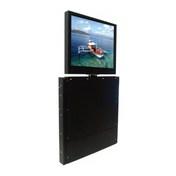
This feature completely conceals the unit when in its stowed position inside the cabinet or credenza. The FD201LIFT utilizes a state of the art digital video decoding chipset for the analog video input. There are three video source inputs available. They are in order of picture quality: (1) VGA (computer graphics like Moving Maps), (1) S- Video, (1) Composite Video (DVD, camera or VCR). -
Page 6: Display Specifications
All manuals and user guides at all-guides.com The FD201LIFT can turn up to 90° either way. It also features two worm gears which can be adjusted with a flat head screwdriver to limit the amount of travel from left to right. One revolution equates approximately 5 degrees of adjustment. -
Page 7: Physical Specifications
Double Pole, Double Throw Installation Instructions All cabin entertainment equipment, such as the FD201LIFT should be installed on a non-essential bus and have a dedicated circuit breaker. It is a requirement that a switch be installed in the cockpit so that the pilot can de-energize the entertainment system should it become necessary. -
Page 8: Video Wiring Suggestions
All manuals and user guides at all-guides.com Video Wiring Suggestions All shields should be grounded to the connector at the source, and floating at the display. Avoid routing video wiring parallel to: • AC wiring • Strobe wiring • DC motor supply cables •... -
Page 9: Vga Wiring
All manuals and user guides at all-guides.com VGA Wiring Recommended cable for VGA purpose is ECS P/N 453005. This is a single shielded cable containing 5 separate coaxial cables, color-coded to match the functions of the wires. The individual wires should be extended with 6” 22awg wires using an environmental splice for the red &... -
Page 10: Power And Ground Wiring
All manuals and user guides at all-guides.com Pinout for High Density DB-25 (J1 – LCD Power, Lift Power, Video) Part Numbers for DB-25 connector & pins, manufactured by Tyco or Amp. D-sub, 25 contact receptacle (female) P/N 207463-1 DB25-F pins P/N M39029/63-368 Wiring Diagram Description... -
Page 11: Pinout For Db-25 (J1 - Lcd Power, Lift Power, Video)
All manuals and user guides at all-guides.com Control Switch Diagram In order to raise the lift, Pin 22 must be supplied 18VDC power, and Pin 18 should be supplied 18VDC ground. To lower, Pin 22 must be supplied 18VDC ground, and Pin 19 should be supplied 18VDC power. Below is an example of wiring a DPDT switch for this purpose. -
Page 12: Operation Instructions
No pilot or aircrew action is necessary during flight or ground operation. The passengers will be able to change the video output from the FD201LIFT using the video source select button with the included IR remote. Point the IR remote towards the top of the LCD to cycle thru the different sources. -
Page 13: Rs-485 Control
All manuals and user guides at all-guides.com Button Controls Located at the bottom (right) of the monitor are 8 buttons. Their functions are shown below: BUTTON DESCRIPTION POWER Toggles the power ON or OFF. Also, wakes the display up from SLEEP mode. MENU Opens the MENU. -
Page 14: Rs-485 Network
All manuals and user guides at all-guides.com Remote Control Buttons BUTTON DESCRIPTION POWER Toggles the power ON or OFF. Also, wakes the display up from SLEEP mode. MENU Opens the MENU. DOWN Moves to the next selection in the menu. Moves to the previous selection in the menu. -
Page 15: Troubleshooting
All manuals and user guides at all-guides.com Troubleshooting Video Noise Check for an incorrect ground in the installation wiring. See specific examples of video noise below, or visit http://flightdisplay.com/Grounding.pdf VGA Shadowing Most of shadowing problems are due to shielding on the wire. Locate the point where all of the shields are connected. -
Page 16: Color Distortion
For further product information, technical data and sample wiring diagrams, please click on the Dealers section of our web site at www.flightdisplay.com Instructions for Continued Airworthiness The FD201LIFT is designed not to require regular general maintenance. Revision B, April 2009 ... -
Page 17: Warranty Information
867-6717 to obtain assistance. If the return of the unit to the factory is required, an RMA number will be issued at that time. Flight Display Systems will, upon receipt of the failed hardware, remanufacture or replace the unit at our discretion. - Page 18 All manuals and user guides at all-guides.com Assembly Drawings Revision B, April 2009 ...
- Page 19 All manuals and user guides at all-guides.com 15 Revision B, April 2009 ...
- Page 20 All manuals and user guides at all-guides.com Index Coaxial Cable ........5 Remote Control......12, 14 Color Distortion......14 Shadowing........13 Continued Airworthiness ..... 14 Shields .......... 5, 13 DB-25..........7 Support ........14, 15 DO-160 ..........2 VGA............ 5 Flammability ........
- Page 21 All manuals and user guides at all-guides.com Log of Revisions Date Page Description 12/10/2008 Initial Release 04/13/2009 2,3,13 Updated specifications, warranty info 17 Revision B, April 2009 ...
Need help?
Do you have a question about the FD201LIFT and is the answer not in the manual?
Questions and answers