Advertisement
Quick Links
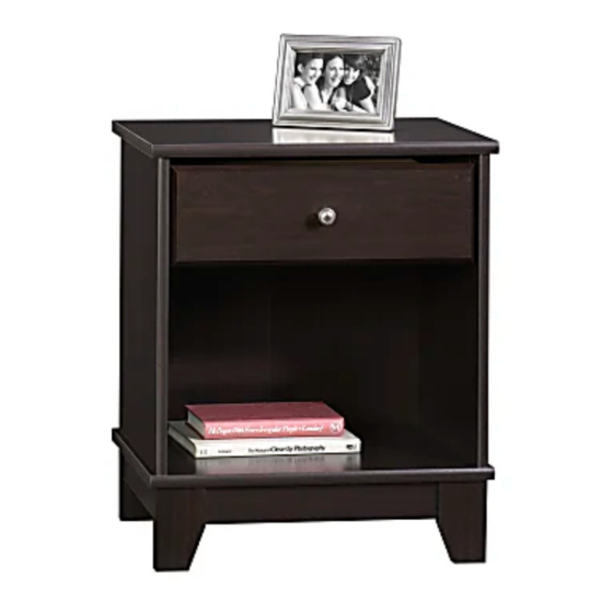
414259
Side Table
Camarin Collection
PLEASE CONTACT US
BEFORE RETURNING
YOUR UNIT TO THE STORE
1-800-523-3987
www.sauder.com
NOTE: THIS INSTRUCTION BOOKLET CONTAINS
IMPORTANT SAFETY INFORMATION.
PLEASE READ AND KEEP FOR FUTURE REFERENCE.
English .................... Page 1-15
Français ...............Pages 16-18
Made in the USA
Espanol .............Páginas 19-21
Archbold, OH
Lot #: 353014
Date Purchased: ____________________
05 / 08 / 13
Advertisement

Related Manuals for Sauder Camarin Series


Summary of Contents for Sauder Camarin Series
- Page 1 PLEASE READ AND KEEP FOR FUTURE REFERENCE. BEFORE RETURNING English ....Page 1-15 YOUR UNIT TO THE STORE Français ....Pages 16-18 Made in the USA 1-800-523-3987 Espanol .....Páginas 19-21 Archbold, OH www.sauder.com Lot #: 353014 05 / 08 / 13 Date Purchased: ____________________...
-
Page 2: Table Of Contents
ADULT ASSEMBLY REQUIRED Part Identifi cation .......3 Hardware Identifi cation .....4 ASSEMBLY TOOLS REQUIRED Assembly Steps ....5-15 No. 2 Phillips Screwdriver Français ......16-18 Tip Shown Actual Size Espanol ....... 19-21 Safety ........22 Hammer Warranty ........23 Page 2 www.sauder.com/services 414259... -
Page 3: Part Identification
Use this PART IDENTIFICATION to help identify similar parts. RIGHT END DRAWER LEFT SIDE SIDE SKIRT LEFT END DRAWER BACK DRAWER FRONT LEFT FRONT/RIGHT D720 DRAWER BOTTOM REAR FOOT BOTTOM BACK RIGHT FRONT/LEFT REAR FOOT DRAWER RIGHT SIDE FRONT SKIRT D720 414259 www.sauder.com/services Page 3... -
Page 4: Hardware Identification
BLACK 1-7/8" FLAT HEAD SCREW - 4 GOLD 5/16" FLAT HEAD SCREW - 8 BLACK 1-9/16" FLAT HEAD SCREW - 4 GOLD 1" MACHINE SCREW - 1 Screws are shown actual size. You may receive extra hardware with your unit. Page 4 www.sauder.com/services 414259... -
Page 5: Assembly Steps
Look for this icon. It means a video assembly tip is available at: www.sauder.com/services/tips Do not tighten the HIDDEN CAMS in this step. Arrow Arrow (4 used) Insert the metal end of the CAM DOWEL into the HIDDEN CAM. (4 used) Assemble your unit on a carpeted fl... - Page 6 (4 used in this step) Fasten a CABINET RIGHT (35GA) to the RIGHT END (A) and a CABINET LEFT (35GB) to the LEFT END (B). Use four GOLD 5/16" FLAT HEAD SCREWS (3S) through holes #1 and #3. Page 6 www.sauder.com/services 414259...
- Page 7 Tighten Arrow Risk of damage or injury. Hidden Cams must be completely Arrow Maximum tightened. Hidden 210 degrees Cams that are not completely tightened Minimum may loosen, and parts 190 degrees may separate. To completely tighten: 414259 www.sauder.com/services Page 7...
- Page 8 Fasten the SKIRT (F) to the BOTTOM (D). Use two BLACK 9/16" LARGE HEAD SCREWS (1S). Insert two METAL PINS (1R) into the short edges of the SKIRT. Push the FRONT FEET (R and S) onto the METAL PINS. Page 8 www.sauder.com/services 414259...
- Page 9 Fasten four CORNER BRACKETS (31G) to the BOTTOM (D). Use eight BLACK 9/16" LARGE HEAD SCREWS (1S). Fasten the two front CORNER BRACKETS to the FRONT FEET (R and S). Use four BLACK 9/16" LARGE HEAD SCREWS (1S). 414259 www.sauder.com/services Page 9...
- Page 10 Fasten the SIDE SKIRTS (G) to the CORNER BRACKETS (31G). Use eight BLACK 9/16" LARGE HEAD SCREWS (1S). Fasten the REAR FEET (R and S) to the CORNER BRACKETS. Use four BLACK 9/16" LARGE HEAD SCREWS (1S). Page 10 www.sauder.com/services 414259...
- Page 11 Carefully turn your unit over onto its front edges. Unfold the BACK (E) and lay it over your unit. Make equal margins along all four edges of the BACK (E). Push on opposite corners of your unit if needed to make it “square”. Fasten the BACK (E) to your unit using the NAILS (1N). 414259 www.sauder.com/services Page 11...
- Page 12 Slide the DRAWER BOTTOM (D720) into the grooves in the DRAWER SIDES (D16 and D17) and DRAWER FRONT (H). Fasten the DRAWER BACK (D73) to the DRAWER SIDES (D16 and D17). Use four BLACK 1-9/16" FLAT HEAD SCREWS (30S). Page 12 www.sauder.com/services 414259...
- Page 13 SIDE (D17). Use four GOLD 5/16" FLAT HEAD SCREWS (3S) through holes #1 and #3. NOTE: The screw head in the CAM must be visible through the slotted hole in the SLIDE. Fasten the KNOB (48K) to the DRAWER FRONT (H). Use the GOLD 1" MACHINE SCREW (50S). 414259 www.sauder.com/services Page 13...
- Page 14 To insert the drawer into your unit, tip the front of the drawer down and drop the rollers on the drawer behind the rollers on the unit. Lift the front of the drawer up and slide it into the unit. Page 14 www.sauder.com/services 414259...
- Page 15 Tighten the SCREW when finished with adjustments. NOTE: Please read the back pages of the instruction booklet for important safety information. This completes assembly. To clean your unit, dampen a cloth with tap water and wipe. 414259 www.sauder.com/services Page 15...
-
Page 16: Français
VIS TÊTE PLATE 8 mm DORÉE ..8 et conserver le livret 30S VIS TÊTE PLATE 40 mm NOIRE ..4 pour future référence. Pour contacter Sauder 50S VIS À MÉTAUX 25 mm DORÉE ..1 en ce qui concerne cet élément, faire référence au numéro de lot et... - Page 17 Veiller à avoir des marges égales le long des quatre chants de l'ARRIÈRE (E). Si besoin est, enfoncer sur les coins opposés de l'élément pour s'assurer d'être « d'équerre ». Fixer l'ARRIÈRE (E) à l'élément à l'aide des CLOUS (1N). 414259 www.sauder.com/services Page 17...
- Page 18 Fixer le BOUTON (48K) au DEVANT DE TIROIR (H). Utiliser la VIS À MÉTAUX 25 mm DORÉE (50S). Ceci complète l'assemblage. Pour nettoyer l’unité, humidifi er un chiffon avec de l’eau du robinet et essuyer. Page 18 www.sauder.com/services 414259...
-
Page 19: Espanol
TORNILLO DORADO DE CABEZA Si necesita ponerse PERDIDA de 8 mm ......8 en contacto con 30S TORNILLO NEGRO DE CABEZA Sauder en cuanto a PERDIDA de 40 mm ......4 esta unidad, refi érase al número de lote y 50S TORNILLO DORADO PARA METAL al número de modelo... - Page 20 Los márgenes a lo largo de todos los bordes del DORSO (E) deben estar uniformes. Empuje sobre las esquinas opuestas de la unidad si es requerido para hacerla "cuadrada." Fije el DORSO (E) a la unidad utilizando los CLAVOS (1N). Page 20 www.sauder.com/services 414259...
- Page 21 CORREDERA. Fije el POMO (48K) a la CARA DE CAJÓN (H). Utilice el TORNILLO DORADO PARA METAL de 25 mm (50S). 414259 www.sauder.com/services Page 21...
-
Page 22: Safety
Además, el peso y la ubicación del tubo de imagen tienden a causar la inestabilidad de televisores y son propensos a inclinarse hacia adelante. Page 22 www.sauder.com/services 414259... -
Page 23: Warranty
4. La présente garantie ne s’applique qu’aux défauts garantis qui se produisent des composantes de mobilier Sauder. Le mot « défaut », tel qu’il est utilisé sous pour la première fois et qui sont signalés à Sauder dans les limites de ouverture les termes de la présente garantie, comprend les imperfections des pièces qui... - Page 24 Archbold, Ohio, where it all began. Certifi cate of Conformity The Sauder name on the box ensures that 1. This certifi cate applies to the Sauder Woodworking Product identifi ed by this Instruction Book. the item you have purchased is made with 2.
Need help?
Do you have a question about the Camarin Series and is the answer not in the manual?
Questions and answers