
Subscribe to Our Youtube Channel
Related Manuals for Chrysler 4469106


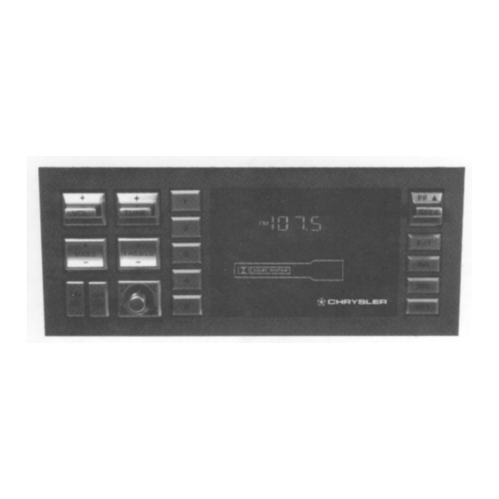
Summary of Contents for Chrysler 4469106
- Page 3 Voltaae Tuned Circuits capacitances in 'the AM tuner module varactors and D3, changes resonant frequencies their circuits changed. When associated varactor fails, replace the U2 module. FM varactors, located in module lJ4, change when the voltage applied across them changes their resonant frequencies...
-
Page 4: Pin Number
TABLE 1-3. MICROPROCESSOR (UlOO) PIN DESCRIPTIONS PIN NUMBER DESCRIPTION Key Input KO Key Input Kl Key Input K2 Key Input K3 Radio Test Pin Frequency Synthesizer Enable - Allows data transfer to the Frequency Synthesizer Beep Output Soft mute goes low to turn on Q102 Reset Input - A high on this pin for 6 usec . - Page 5 MICROPROCESSOR (UlOO) PIN DESCRIPTIONS (Cont.) TABLE 1-3. DESCRIPTION PIN NUMBER Cassette read enable Cassette write enable Mono - Goes low for force to mono Station detect - goes low for station Joystick enable Stereo Detect - goes low for stereo Display Driver Enable - Allows data to be transferred to the vacuum fluorescent display driver.
- Page 6 TABLE l-4. SYNTHESIZER (U102) PIN DESCRIPTIONS PIN NUMBER DESCRIPTION Goes high during the search mode, to desensitize the front end to very weak stations. Noise Reduction (high = NR on) Serial data from the microprocessor Data clock from the microprocessor Data enable from the microprocessor Switched supply voltage which is regulated by U103, a 5 volt regulator.
- Page 7 SYNTHESIZER (U102) PIN DESCRIPTIONS (CONT.) TABLE l-4. DESCRIPTION PIN NUMBER Charge pump output develops tuning voltages and op-amp input. Operational amplifier output - Supplies the tuning voltage for the RF circuits. Operational amplifier ground. Switched supply voltage, 10 volts. Power-On-Reset - The power-on-reset is controlled by UlOl, see Table l-5.
- Page 8 AM CIRCUIT RF Stage - The AM signals received by the antenna are coupled through the series choke Ll, which presents a high impedance to FM and shortwave broadcast frequencies, and Cl to AM antenna coil Tl which transformer couples the RF signal to the gate of Ql a J-FET RF amplifier.
- Page 9 Detector and AM Stereo Decoder (Cont.) receivers. The phase compatible with monaural modulation components of a quadrature signal are extracted and used to phasemodulate the broadcast The (L-R) information is contained in transmitter. this quadrature phase modulation. The (L+R) is The chip automatically transmitted as normal AM.
- Page 10 Detector and AM Stereo Decoder (Cont.) During AM operation, transistors Q5 and Q6 conduct to apply the regulated 10 volts to pin 6 of U3. The AM audio outputs pin 7 (left) and pin 8 (right) are applied to the filter/Amp IC (U7). FM CIRCUIT FM Front End - The completely integrated FM front end, U4, performs the following functions AGC, RF...
-
Page 11: Audio Circuit
Stereo Decoder and Blend (Cont.) blend and high frequency rolloff circuit controlled This by the IF AGC voltage at pins 7 and 5. feature improves the S/N of very weak stereo station by gradually reducing the separation and The blend threshold is high frequency response. - Page 12 Electronic - Volume. Tone, Balance and Fader (Cnt) through Cl06 to pin 10 and through Cl07 to pin 19. The chosen input source is passed through external capacitors and on pins 13 and 16 to the DNR chip and it comes back in on pins 14 and 15 through The operation of U105 C120, C122;...
-
Page 13: Mechanism Control Board
CLOCK The clock function is derived from the synthesizer on-chip osc illator which is stabilized by a 3.96 MHz quartz crystal (X100). Capacitor Cl31 is a fine tuning trimmer for setting As an example, if the oscillator frequency the clock accuracy. was 392 Hz low (196 Hz low at U102 pin 14), this would cause This same degree of the clock to lose one minute per week. - Page 18 U 1 0 1 U102 DC V ” D C V DC V 4.95 4.70 4.95 5.27 4.95 1.65 4.95 4.70 1.65 1 . 8 5 1.85 4.9s 4.95 3.85 3.85 4.95 4.9s 4.90 3.80 1.40 1.40 4.30 4.70 4.3s 2.85 2.50 4.50...
- Page 19 U101 "102 U100 DC V D C V D C " D C V 4.95 4.70 4.95 5.27 4.95 4.70 1.55 1.65 4.95 1.85 4.95 1.85 3.85 3.85 4.95 4.95 4.95 4.90 2.80 1.40 1.40 2.85 4.20 4.70 4.35 2.50 4.50 4.70 4.70...
Need help?
Do you have a question about the 4469106 and is the answer not in the manual?
Questions and answers