Table of Contents
Advertisement
Quick Links
Advertisement
Table of Contents

Related Manuals for TYAN GT93-B7106

Summary of Contents for TYAN GT93-B7106
- Page 1 GT93-B7106 Service Engineer’s Manual http://www.tyan.com...
- Page 2 http://www.tyan.com...
- Page 3 MITAC assumes no liability whatsoever, and ® disclaims any express or implied warranty, relating to sale and/or use of TYAN products including liability or warranties relating to fitness for a particular purpose or merchantability. MITAC retains the right to make changes to produce descriptions and/or specifications at any time, without notice.
- Page 4 This Class A digital apparatus complies with Canadian ICES-003. Cet appareil numérique de la Classe A est conforme à la norme NMB-003 du Canada. Notice for Europe (CE Mark) ● This product is in conformity with the Council Directive 2014/30/EU and 2014/35/EU. http://www.tyan.com...
- Page 5 Replace only with the same or equivalent type recommended by manufacturer. Dispose of used battery according to manufacturer instructions and in accordance with your local regulations. VCCI-A ● この装置は、クラスA機器です。この装置を住宅環境で使用すると電波妨害を引き 起こすことがあります。この場合には使用者が適切な対策を講ずるよう要求される VCCI-A ことがあります。 Safety: IEC/EN 60950-1 ● This equipment is compliant with CB/LVD of Safety: IEC/EN 60950-1. http://www.tyan.com...
- Page 6 About this Manual This manual is intended for skilled person with hardware knowledge of computers. It is aimed to provide you with instructions on installing your TYAN GT93-B7106. How this guide is organized This guide contains the following parts: Chapter 1: Overview...
- Page 7 Safety and Compliance Information Before installing and using TYAN GT93-B7106, take note of the following precautions: ·Read all instructions carefully. ·Do not place the unit on an unstable surface, cart, or stand. ·Do not block the slots and opening on the unit, which are provided for ventilation.
- Page 8 You must become familiar with the safety information in this guide before you install, operate, or service TYAN products. Symbols on Equipment Caution. This symbol indicates a potential hazard.
- Page 9 · Do not attempt to move a fully loaded rack. Remove equipment from the rack before moving it. · Do not attempt to move a rack on an incline that is greater than 10 degrees http://www.tyan.com...
- Page 10 This will reduce the risk of personal injury, fire, or damage to the equipment. The total rack load should not exceed 80 percent of the branch circuit rating. Consult the electrical authority having jurisdiction over your facility wiring and installation requirements. http://www.tyan.com...
- Page 11 TYAN, your authorized TYAN partner, or their agents. Equipment Modifications · Do not make mechanical modifications to the system. TYAN is not responsible for the regulatory compliance of TYAN equipment that has been http://www.tyan.com...
- Page 12 – The product does not operate normally when you follow the operating instructions. · Retain all screws or other fasteners when removing access cover(s). Upon completion of accessing inside the product, refasten access cover with original screws or fasteners. http://www.tyan.com...
-
Page 13: Table Of Contents
Table of Contents Chapter 1: Overview............... 15 About the TYAN GT93-B7106 ..........15 Product Models ............... 15 Features .................. 16 Standard Parts List ..............20 1.4.1 Box Contents and Accessories ........20 About the Product ..............21 ... - Page 14 Appendix I: How to recover UEFI BIOS ........79 Appendix II: Cable Connection Tables ......... 81 Appendix III: Fan and Temp Sensors ........... 83 Appendix IV: FRU Parts Table ............87 Appendix V: Technical Support ............ 89 http://www.tyan.com...
-
Page 15: Chapter 1: Overview
® TYAN also offers the GT93-B7106 in a version that can support up to twelve (12) internal easy-swappable 2.5”/3.5” SSD/HDD and one (1) internal easy-swappable 2.5” SSD. The GT93-B7106 uses TYAN’s latest chassis featuring a robust structure and a solid mechanical enclosure. -
Page 16: Features
Features TYAN GT93-B7106 (B7106G93V13R) Form Factor 1U Rackmount Chassis Model GT93 Chassis Dimension 37.0" x 17.3" x 1.7" (D x W x H) (940 x 440 x 43.3mm) System Motherboard Name S7106GM2NR Gross Weight 21 kg (46.5 lbs) Net weight 15.5 kg (34.5 lbs) - Page 17 Notification Intel Optane DC Persistent Memory Module (DCPMM) only supported with specific 2nd Gen Intel Xeon Scalable Processor (codename: Cascade Lake). Please contact Tyan Technical Support for more detail. PCI-E (1) PCI-E Gen3 x16 slot (FH, HL) Pre-install TYAN (1) M7106-L16-1F for (1) PCI-E...
- Page 18 AMI, 32MB Hardware Monitor, SMBIOS 3.0/PnP/Wake on LAN, Boot from BIOS USB device/PXE via LAN/Storage, Feature Console Redirection, ACPI sleeping states S4,S5, ACPI 6.1, FAN speed control automatic Please refer to our AVL support Operating System OS supported list lists. http://www.tyan.com...
- Page 19 In/Non-operating 90%, non-condensing at 35° C Humidity RoHS RoHS 6/6 Compliant Barebone (1) GT93-B7106 Barebone Package Contains Manual (1) Quick Installation Guide NOTE: 1. The specifications are subject to change without prior notice. 2. Please visit our Web site for the latest specifications.
-
Page 20: Standard Parts List
Standard Parts List This section describes GT93-B7106 package contents and accessories. Open the box carefully and ensure that all components are present and undamaged. The product should arrive packaged as illustrated below. 1.4.1 Box Contents and Accessories If any items are missing or appear damaged, contact your retailer or browse to TYAN’s website for service:... -
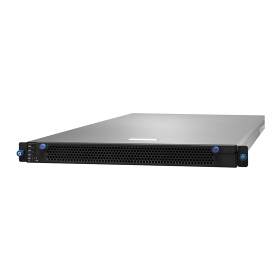
Page 21: About The Product
About the Product The following views show you the product. 1.5.1 System Front View Description Power Button Unit ID Button Reset Button Power LED (green) HDD LED (green) Warning LED (amber) Unit ID LED (blue) http://www.tyan.com... - Page 22 PSU voltage sensor over threshold alert PSU current sensor PSU power sensor PSU 1+1 Redundancy Warning LED Indications PSU Status Warning LED 2 PSUs are present and system is on 1 PSU AC lost Solid On 1 PSU absent Solid On http://www.tyan.com...
-
Page 23: System Rear View
1.5.2 System Rear View Description PSU1 PSU0 IPMI LAN USB3.0 Ports COM Port LAN2 LAN1 OCP Card Area UID Button Low profile PCIE x16 Slot BMC Heartbeat LED http://www.tyan.com... -
Page 24: Psu And Lan Led Indications
Green Solid On Green Solid On 100 Mbps Active Green Blinking Green Solid On Link Green Solid On Amber Solid On 1000 Mbps (1Gbps) Active Green Blinking Amber Solid On NOTE: “Left” and “Right” are viewed from the rear panel. http://www.tyan.com... -
Page 25: System Top View
1.5.4 System Top View Description Description 2.5”/3.5” SSD/HDD Trays Power Supply Modules M1723G86-FPB Riser Card Bracket (pre-installed) (M7106-L16-1F pre-installed) System Fans 2.5” SSD Tray M1625G93-D-PDB M7106G93-BP6-4 HDD BP Board (pre-installed) (per-installed) http://www.tyan.com... -
Page 26: Chassis Dimensions
1.5.5 Chassis Dimensions http://www.tyan.com... -
Page 27: Board Image (S7106)
1.5.6 Board Image (S7106) http://www.tyan.com... -
Page 28: Block Diagram
1.5.7 Block Diagram http://www.tyan.com... -
Page 29: Chapter 2: Setting Up
Caution! To avoid damaging the motherboard and associated components, use torque force within the range kgf/cm (4.35 ~ 6.09 lb/in) on each mounting screw for motherboard installation. Do not apply power to the board if it has been damaged. http://www.tyan.com... -
Page 30: Precautions
Working on a system that is connected to a power supply can be extremely dangerous. Follow the guidelines below to avoid damage to GT93-B7106 or injury to yourself. Ground yourself properly before removing the top cover of the system. -
Page 31: Installing Motherboard Components
This section describes how to install components on to the motherboard, including CPUs, memory modules and Add-on cards. 2.1.1 Removing the Chassis Cover Follow these instructions to remove the GT93-B7106 chassis cover. Loosen the thumb screws on the front panel. 2. Slide forwards to lift up the top cover. http://www.tyan.com... -
Page 32: Replacing The Chassis Cover
2.1.2 Replacing the Chassis Cover Follow these instructions to replace the GT93-B7106 chassis cover. Place the top cover on the chassis and slide it backwards. Secure the top cover by tightening the thumbscrew. NOTE: The thumbscrews should be tightened with a screwdriver after the top chassis is closed. -
Page 33: Installing The Cpu And Heat Sink
Carefully flip the heatsink. Then install the carrier assembly on the bottom of the heatsink and make sure the gold arrow is located in the correct direction. Locate the CPU socket’s guide pin. Always start with CPU0 first. Remove the CPU Socket protection cap. http://www.tyan.com... - Page 34 To secure the heatsink, use a T30 Security Torx to tighten the screws in a sequential order (1234). NOTE: When disassembling the heatsink, loosen the screws in reverse order (4321). Repeat the procedures described earlier to install the second processor and heatsink. http://www.tyan.com...
-
Page 35: Installing The Memory
Press the memory slot locking levers in the direction of the arrows as shown in the following illustration. Align the memory module with the slot. When inserted properly, the memory slot locking levers lock automatically onto the indentations at the ends of the module. http://www.tyan.com... - Page 36 2. Use paired memory installation for max performance. 3. Populate the same DIMM type in each channel, specifically - Use the same DIMM size - Use the same # of ranks per DIMM 4. Always install with CPU0 Socket first. http://www.tyan.com...
- Page 37 √ √ √ √ √ √ P1_MC0_DIM_CH_B1 √ P1_MC0_DIM_CH_B0 √ √ √ √ √ √ √ P1_MC0_DIM_CH_C0 √ √ √ √ P1_MC1_DIM_CH_D0 √ √ √ √ √ P1_MC1_DIM_CH_E1 √ P1_MC1_DIM_CH_E0 √ √ √ √ √ P1_MC1_DIM_CH_F0 √ √ √ http://www.tyan.com...
-
Page 38: Installing The Expansion Card
2.1.5 Installing the Expansion Card Follow these instructions to install the expansion card. Unlock the knob to lift up the 2.5” SSD/HDD tray and the Riser Card Bracket. Unscrew to remove the dummy bracket. http://www.tyan.com... - Page 39 Insert the expansion card into the riser card bracket and secure with a screw. Replace the Riser Card Bracket into the chassis. http://www.tyan.com...
-
Page 40: Installing The Ocp Mezz Card
Take out the OCP Mezz LAN Card and align with the IO Port opening in the OCP Card Area. Install the OCP Mezz LAN Card into the IO Port opening. Place the air duct on top of the OCP Mezz LAN card and secure with four screws. http://www.tyan.com... -
Page 41: Installing The 2.5" Hard Drive (At Rear)
Follow these instructions to install the 2.5” SATA SSD/HDD. Unlock the knob and place the 2.5” SSD/HDD tray on top of the OCP Card Area. Locate the guide pins. Align and install the SSD module on top of the SSD tray. Then retract the tray. http://www.tyan.com... - Page 42 Connect the cable to the connector on the SSD module and secure the SSD tray knob. http://www.tyan.com...
-
Page 43: Installing The 2.5" Or 3.5" Hard Drives
2.1.8 Installing the 2.5” or 3.5” Hard Drives The GT93-B7106 supports twelve 2.5”/3.5” SATA SSDs/HDDs. Follow these instructions to install a hard drive. Pull up and slightly push forward to release the HDD tray. Then remove the HDD tray from the chassis. - Page 44 Take out the screw pack from the AK box. Flip over the HDD tray and secure with four screws as illustrated. 2.5” HDD SCREW P/N: 372000000013 3.5” HDD SCREW P/N: 371000000406 Carefully install the HDD assembly to the chassis and check if it is connected properly. http://www.tyan.com...
-
Page 45: Rack Mounting
Rails x 2 Screw Sacks x 2 2.2.1 Installing the Server in a Rack Follow these instructions to mount the GT93-B7106 into an industry standard 19” rack. Note: Before mounting GT93-B7106 in a rack, ensure that all internal components have been installed and that the unit has been fully tested. -
Page 46: Installing Slide Rails To The Rack
Take out the rails from the accessory kit. Push the tab in the direction as the arrow shows to draw out the inner rails. Attach the inner rails to both sides of the chassis. Push the inner rails backward to lock in place. http://www.tyan.com... - Page 47 Attach the outer rail to the rack. Pull the latch open and align the square stud with the square hole on the rack rail. Please note that the square stud must be fully attached inside the square hole and then close the latch to lock. Rear http://www.tyan.com...
- Page 48 Front Repeat the same procedures for the other side. http://www.tyan.com...
-
Page 49: Rack Mounting The Server
Must be done with at least 2 people. Properly place the chassis directly on the rack and install. Slide in the chassis half way to the lock position. Push the blue tabs forward to slide the chassis all in. http://www.tyan.com... - Page 50 Fasten the chassis ear to the front surface of chassis. http://www.tyan.com...
-
Page 51: Removing The Server From Rack
Pull out the chassis half way to the lock position. Push the white locking tabs forward to slide the chassis all out from the rack. Caution: Remove the server from the rack carefully. Must be done with at least 2 people. http://www.tyan.com... - Page 52 NOTE http://www.tyan.com...
-
Page 53: Chapter 3: Replacing Pre-Installed Components
This chapter explains how to replace the pre-installed components, including the S7106 Motherboard, M1723G86-FPB Front Panel Board, M7106-L16-1F Riser Card, M7106G93-BP6-4 HDD Backplane Board, M1625G93-D-PDB Power Distribution Board, System Fan and Power Supply etc. Disassembly Flowchart The following flowchart outlines the disassembly procedure. http://www.tyan.com... -
Page 54: Removing The Cover
Removing the Cover Follow Chapter 2.1.1 to remove the cover of GT93-B7106. Replacing the Power Supply To replace the power supply follow these instructions. Press the latch as shown to pull out the power supply module. Replace a new single power and reinsert it into the power cage following the above steps in reverse. -
Page 55: Replacing The Front Panel Board
Follow these instructions to replace the M1723G86-FPB Front Panel Board. Loosen three screws and disconnect the front panel cable. After replacing with a new Front Panel Board, follow the steps described earlier in reverse order to reinstall the front panel board module. http://www.tyan.com... -
Page 56: Front Panel Board Features
Front Panel Board Features M1723G86-FPB Front Panel Board Form Factor 39x50x1.6mm, 4 layer PCB (1) Signal Connector (J5) #1: PWR Button #2: UID Button Integrated I/O #3: Reset Button #4: PWR LED / #6: Warning LED #5: HDD LED / #7: UID http://www.tyan.com... -
Page 57: Replacing The Hdd Backplane Board
Release the cable tie to disconnect cables. Unscrew to remove the HDD BP Board. After replacing with a new HDD Backplane Board, follow the procedures described earlier in reverse order to reinsert the HDD Backplane Board into the chassis. http://www.tyan.com... -
Page 58: Hdd Bp Board Features
HDD BP Board Features Front View Rear View M7106G93-BP6-4 HDD Backplane Board Form Factor , 4 layer 380mm*16mm*23.7mm (1) 1x4P Power connector (PW2) Integrated I/O (1) Mini SAS Connector to MB (J3) (4) SAS/SATA Connector (J1, J2, J4, J5) http://www.tyan.com... -
Page 59: Replacing Power Distribution Board
Disconnect all cables connected to the Power Distribution Board. Pull the power supply modules slightly away from the chassis. Unscrew to replace the M1625G93-D-PDB Power Distribution Board. Follow the steps described earlier in reverse order to reinstall the power distribution board into the chassis. http://www.tyan.com... -
Page 60: Power Distribution Board Features
3.7.1 Power Distribution Board Features M1625G93-D-PDB Power Distribution Board Form Factor 122mm*105.6mm*35.1mm, 6 layer Specifications 1+1 PSU redundancy PDB for DELTA DPS-650AB-14D http://www.tyan.com... -
Page 61: Connector Definitions
Power supply slot PWR1 Micro-fit Power 12x2 Micro-fit Power 4x1 Micro-fit Power 4x1 Micro-fit Power 4x1 PW10 Micro-fit Power 4x1 PW11 Micro-fit Power 4x1 Micro ATX Power 4x2 Micro ATX Power 4x2 Micro-fit Power 4x2 PMBUS SYS_FAN_2 FAN 4x1 http://www.tyan.com... -
Page 62: Replacing The Riser Card
Follow these instructions to replace the M7106-L16-1F Riser Card. Lift up the Riser Card Bracket from the chassis. Unscrew to replace with a new riser card. Follow the steps described earlier in reverse order to reinstall the riser card bracket. http://www.tyan.com... -
Page 63: Riser Card Feature
3.8.1 Riser card Feature M7106-L16-1F Riser Card 123mm*29.7mm*15.4mm, 4 layer Form Factor PCI-E x16 Gen3 adapter card Specification (1) PCI-E x16 Gen3 slot support (1) PCI-E x16 Add-on card http://www.tyan.com... -
Page 64: Replacing The Fan
Place the new fan into the chassis and reconnect the fan cable. Please refer to the following picture for fan connector locations on the mainboard. Check if the fan module is properly installed. NOTE: Remember to tie cables after fan replacement. http://www.tyan.com... - Page 65 http://www.tyan.com...
-
Page 66: 3.10 Replacing The Motherboard
3.10 Replacing the Motherboard After removing all of the aforementioned components, follow these instructions to remove the motherboard from the chassis. Disconnect all cables. Unlock the knob to lift up the Riser Card Bracket and 2.5” SSD/HDD tray. http://www.tyan.com... - Page 67 Unscrew the motherboard to lift it up for replacement. http://www.tyan.com...
- Page 68 NOTE http://www.tyan.com...
-
Page 69: Chapter 4: Diagnostics
BIOS flash failure, you must contact your dealer for a replacement BIOS. There are no exceptions. TYAN does not have a policy for replacing BIOS chips directly with end users. In no event will TYAN be held responsible for damages done by the end user. -
Page 70: Amibios Post Code (Aptio)
North Bridge initialization before microcode loading 0x04 South Bridge initialization before microcode loading 0x05 OEM initialization before microcode loading 0x06 Microcode loading 0x07 AP initialization after microcode loading 0x08 North Bridge initialization after microcode loading 0x09 South Bridge initialization after microcode loading http://www.tyan.com... - Page 71 Memory initialization. Serial Presence Detect (SPD) data reading 0x2C Memory initialization. Memory presence detection 0x2D Memory initialization. Programming memory timing information 0x2E Memory initialization. Configuring memory 0x2F Memory initialization (other) 0x30 Reserved for ASL (see ASL Status Codes section below) http://www.tyan.com...
- Page 72 CPU self test failed or possible CPU cache error 0x59 CPU microcode is not found or microcode update is failed 0x5A Internal CPU error 0x5B Reset PPI is not available 0x5C – 0x5F Reserved for future AMI error codes S3 Resume Progress Codes http://www.tyan.com...
- Page 73 Reserved for future AMI error codes PEI Beep Codes # of Beeps Description 1 (repeatedly) Memory not installed Memory was installed twice (InstallPEIMemory routine in PEI Core called twice) Recovery started DXEIPL was not found DXE Core Firmware Volume was not found Recovery failed http://www.tyan.com...
- Page 74 South Bridge DXE initialization (South Bridge module specific) 0x76 South Bridge DXE initialization (South Bridge module specific) 0x77 South Bridge DXE initialization (South Bridge module specific) 0x78 ACPI module initialization 0x79 CSM initialization 0x7A – 0x7F Reserved for future AMI DXE codes http://www.tyan.com...
- Page 75 Start of Setup 0xAA Reserved for ASL (see ASL Status Codes section below) 0xAB Setup Input Wait 0xAC Reserved for ASL (see ASL Status Codes section below) 0xAD Ready To Boot event 0xAE Legacy Boot event 0xAF Exit Boot Services event http://www.tyan.com...
- Page 76 0xDC Reset protocol is not available DXE Beep Codes # of Beeps Description Invalid password Some of the Architectural Protocols are not available No Console Output Devices are found No Console Input Devices are found Flash update is failed http://www.tyan.com...
- Page 77 System is waking up from the S3 sleep state 0x40 System is waking up from the S4 sleep state 0xAC System has transitioned into ACPI mode. Interrupt controller is in PIC mode. 0xAA System has transitioned into ACPI mode. Interrupt controller is in APIC mode. http://www.tyan.com...
- Page 78 NOTE http://www.tyan.com...
-
Page 79: Appendix I: How To Recover Uefi Bios
UEFI recovery bootloader that would prevent the recovery process itself from working. In no event shall Tyan be liable for direct, indirect, incidental, special or consequential damages arising from the BIOS update or recovery. - Page 80 “Flash update completed. Press any key to reset the system” displayed on screen. Remove the USB disk and reboot. If your system does not have video output or the POST code halts at “FF” on the right-lower portion of the screen, please contact Tyan representatives for RMA service. http://www.tyan.com...
-
Page 81: Appendix Ii: Cable Connection Tables
SSATA 0_3 Mini-SAS Cable Mini-SAS HD to → SATA 0_3 Mini-SAS Cable Mini-SAS HD to → SATA 4_7 Mini-SAS Cable 3. FRONT PANEL Cable M1723 FPB to S7106 MB Cable M1723G86-FPB Connect to S7106 → FP CTRL Cable FPIO_1 http://www.tyan.com... - Page 82 → 2x12P Cable PWR1 PWR1 → 2x4P Cable → 2x4P Cable → PSMI Cable PSMI Header M1625 PDB to M7106 BP Cable Connect to M1625G93-D-PDB M7106G93-BP6-4 Micro-Fit 4P → Cable Micro-Fit 4P → PW11 Cable Micro-Fit 4P → Cable http://www.tyan.com...
-
Page 83: Appendix Iii: Fan And Temp Sensors
Fan and Temp Sensor Location: Fan Sensor: It is located in the third pin of the fan connector, which detects the fan speed (rpm) Temp Sensor: Sys_Air_Outlet, Sys_Air_Inlet (on the front panel board), PCH_Temp MB_Air_Inlet. They detect the system temperature around. http://www.tyan.com... - Page 84 BIOS Temp Sensor Name Explanation: http://www.tyan.com...
- Page 85 Temperature of CPU1 DIMM MOSFET_1 P1_DIMM_MOSFET_2 Temperature of CPU1 DIMM MOSFET_2 Max. temperature of CPU0 DIMM channel A P0_MC0_DIM_CH_A Max. temperature of CPU0 DIMM channel B P0_MC0_DIM_CH_B Max. temperature of CPU0 DIMM channel C P0_MC0_DIM_CH_C Max. temperature of CPU0 DIMM channel D P0_MC1_DIM_CH_D http://www.tyan.com...
- Page 86 Fan Speed of System Fan1 SYS_FAN_2 Fan Speed of System Fan2 SYS_FAN_3 Fan Speed of System Fan3 SYS_FAN_4 Fan Speed of System Fan4 SYS_FAN_5 Fan Speed of System Fan5 SYS_FAN_6 Fan Speed of System Fan6 SYS_FAN_7 Fan Speed of System Fan7 http://www.tyan.com...
-
Page 87: Appendix Iv: Fru Parts Table
Appendix IV: FRU Parts Table GT93-B7106 FRU Parts Item Model Number Part Number Picture Description FRU-CS-1300 422T62100001 36-36 pin Mini-SAS HD Cable, 480mm FRU-CS-1310 422T62100004 36-36 pin Mini-SAS HD Cable, 820mm Cable FRU-CS-1320 422T62100005 36-36 pin Mini-SAS HD Cable, 960mm Schuko CEE7/7 >... - Page 88 NOTE http://www.tyan.com...
-
Page 89: Appendix V: Technical Support
MITAC serves multiple market segments with the industry’s most competitive services to support them. Please feel free to contact us directly for this service at tech-support@tyan.com Help Resources: 1. See the beep codes section of this manual. - Page 90 (RMA) number. The RMA number should be prominently displayed on the outside of the shipping carton and the package should be mailed prepaid. TYAN will pay to have the board shipped back to you. TYAN® GT93-B7106 Service Engineer’s Manual V1.0b Document No.: D2494-100...
Need help?
Do you have a question about the GT93-B7106 and is the answer not in the manual?
Questions and answers