
Related Manuals for doble F6300


Summary of Contents for doble F6300
- Page 1 F6300 Power System Simulator User Guide Doble Engineering Company 85 Walnut Street Watertown, Massachusetts 02472-4037 (USA) PN 500-0462 72A-2337-01 Rev. B 11/05...
- Page 2 This Manual is solely the property of the Doble Engineering Company (Doble) and, along with the ProTesT software to which it applies, is provided for the exclusive use of Doble Clients under contractual agreement for Doble test equipment and services.
- Page 3 Warranty Software Limited Warranty Doble warrants that: (i) for a period of one year from the date of shipment from Doble, the media on which the Software is furnished will be free of defects in materials and workmanship under normal use; and (ii) for a period of one year from the date of shipment from Doble, the Software will perform in substantial conformance to its published specifications.
- Page 4 DOBLE. • If DOBLE is unable to deliver replacement disks that are free from defects in materials and workmanship, Purchaser may terminate this agreement. By returning the software product and all copies thereof in any form and affirming compliance with this requirement in writing, DOBLE will refund the purchase price.
-
Page 5: Table Of Contents
Current Sources............................2-2 Auxiliary Functions ............................ 2-3 Communications ..........................2-3 Connecting the F6300 and F6150 ......................2-3 Ethernet 10Base 2 Communications with a “T” Connector ..............2-3 Ethernet 10Base 2 Communication using Terminators ................. 2-5 Ethernet Communication to F6000 Instruments ................... 2-5 Serial Communication to F6000 Instruments .................. - Page 6 Communications Parameters....................... A-3 Appendix B. Configuring Windows for Ethernet Communications ............B-1 Configuring the Control PC........................B-1 Setting the F6300 IP Address ........................B-4 Appendix C. Source Configurations ..............C-1 Current Sources ............................C-1 Rules for Source Selection ......................... C-1 Compliance Voltage and Current Range ....................C-1...
- Page 7 F6300 Power System Simulator User Guide User Defined Configurations ........................C-3 Appendix D. Field Calibration Verification ..........D-1 Testing Specifications..........................D-1 Ambient Accuracy..........................D-1 Test Setup............................D-1 Test Equipment........................... D-1 Testing a 150 VA High Current Source ....................D-2 Testing a 450 VA High Current Source ....................D-3 Phase Shift Testing ............................
- Page 8 72A-2337-01 Rev. B 11/05...
-
Page 9: Introducing The F6300
System Simulator, provides you with realistic power system simulation for protection schemes. The F6300 has two groups of three current sources, six in total. Each source is rated at 150 VA of continuous power or 225 VA of power for 1.5 seconds. Also, each group can be configured as one source at 450 VA of continuous power or 675 VA of power for 1.5 seconds. -
Page 10: Hardware Architecture
The F6300 High Power Current Amplifier (Figure 1.2) is designed to work in conjunction with the F6150 Power System Simulator. The F6150 is responsible for the waveform generation. The F6300 makes the control of the amplifiers available to the F6150 via the Ethernet link and the low level input connection. -
Page 11: Control Panel Version 2
F6300 Power System Simulator User Guide Control Panel Version 2 The F6000 Control Panel Version 2 (Figure 1.3) controls the power system simulator from a computer connected to the instrument’s front panel. It configures and controls the instrument’s voltage sources, current sources, logic inputs, logic outputs, and timers. The F6000 Control Panel Version 2 emulates front panel controls. -
Page 12: What Is Protesttm
ProTesT uses test templates called macros to automate tests on protection scheme relays. The ProTesT database also documents relay settings, test conditions, and test history. Figure 1.4 illustrates how the ProTesT software interacts with the F6150, F6300, and with the relay under test. - Page 13 EMTP or ATP. The DFR and system modeling tool data are typically stored in a COMTRADE file. ProTesT TPlan can work with COMTRADE files and *.pl4 files. To enhance the capabilities of the F6300 instruments, ProTesT: • Automates protective relay tests to reduce testing time and increase accuracy •...
- Page 14 72A-2337-01 Rev. B 11/05...
-
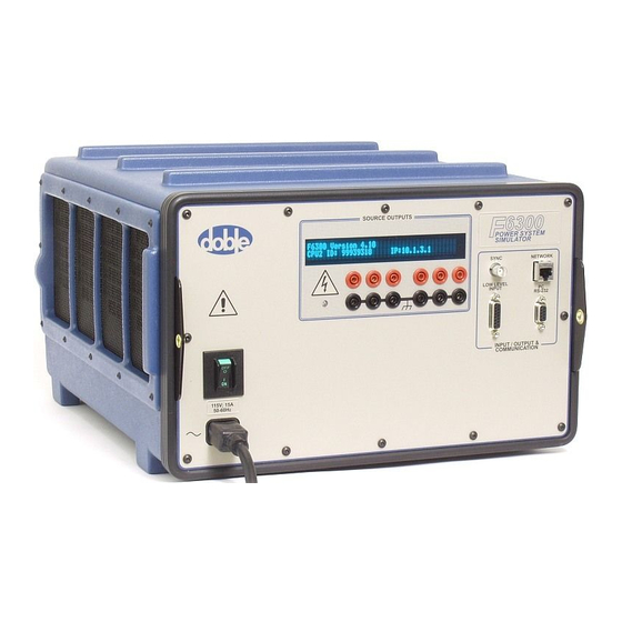
Page 15: F6300 Front Panel
Figure 2.1 Front Panel Figure 2.1 shows an instrument that contains the CPU2 CPU board. The CPU2 F6300 contains a RJ45 CAT5 network connector and the CPU1 F6300 contains a 10 Base 2 network connector. Source Outputs The Source Outputs section of the relay F6300 front panel contains outputs for AC/DC current sources. -
Page 16: Instrument Display
When any source is on, the source label uses an upper case identifier (i.e., I1, I2, and I3.) Current Sources The F6300 provides six 150 VA current sources, which can be combined to achieve more power. Also, three 150 VA current sources can be combined to form a 450 VA source. -
Page 17: Auxiliary Functions
If the control PC is configured for Ethernet communications, it can communicate with the F6300 on a private network using the TCP/IP protocol. When it initiates two-way communication, the PC sends its IP address to the instrument. The F6150, the F6300, and your PC must each have a different IP address assigned. - Page 18 Ethernet 10Base 2 Communications with a “T” Connector Figure 2.2 Connection Using a 10Base2 Connector 72A-2337-01 Rev. B 11/05...
-
Page 19: Ethernet 10Base 2 Communication Using Terminators
1. Connect one of the 50 Ohm terminator to the F6150 network BNC connector. 2. Connect the second 50 Ohm terminator to the F6300 network BNC connector. 3. Connect the supplied RG-58 coax cable to both the F6150 and the F6300. Figure 2.3 A Terminating 10Base2 Connection... - Page 20 Not Applicable Baud Rate Not Applicable IP Address Enter the F6150 IP Default is 10.1.3.1 address Slave Addr Enter the F6300 IP Default is 10.1.3.2 address Connect with Ethernet CAT5 or better Ethernet Cable (401-0243) to/from the Ethernet Port on the 10BaseT/ PC and the HUB.
- Page 21 F6300 Power System Simulator User Guide CAT5 or better Ethernet Cable (401-0243) to/from the Ethernet Port on the PC and the HUB and the HUB to the CPU2 F6150. 10BaseT/10Base2 HUB or 10/100 Switch CPU2 F6150 (401-0244) Figure 2.5 Computer to CPU2 F6150 with Switch/Hub...
- Page 22 NETWORK connector and a 50Ω terminator (401-0157) on the CPU1 F6300 NETWORK connector. CPU1 F6150 CPU1 F6300 Figure 2.7 Computer to CPU1 F6150/CPU1 F6300 CAT5 or better Ethernet Cable (401-0243) to/from the Ethernet Port on the PC and the HUB. 10BaseT/10Base2 HUB...
- Page 23 50Ω terminator (401-0157) on the CPU1 F6150 NETWORK connector. Figure 2.9 Computer to CPU1 F6150/CPU2 F6300 CAT5 or better Ethernet Cable (401-0243) to/from the Ethernet Port on the PC and the HUB and the Hub to the CPU2 F6150.
-
Page 24: Serial Communication To F6000 Instruments
The configurations for serial communications include: • Computer to CPU1 or CPU2 F6150 • Computer to CPU1 F6150/CPU1 F6300 • Computer to CPU2 F6150/CPU2 F6300 with CAT5 Crossover Cable • Computer to CPU2 F6150/CPU2 F6300 with Switch/Hub • Computer to CPU2 F6150/CPU1F6300 •... - Page 25 CPU1 F6300 NETWORK connector. CPU1 F6150 CPU1 F6300 Figure 2.12 Computer to CPU1 F6150/CPU1 F6300 DB9 - DB9 Modem Serial (401-0167) Cable to/from the PC Serial Port or USB- Serial Adapter and the CPU2 F6150 PC RS 232 connector.
- Page 26 HUB and the NETWORK connector on the CPU2 F6300 and the HUB. CPU2 F6300 Figure 2.14 Computer to CPU2 F6150/CPU2 F6300 with Hub/Switch DB9 - DB9 Modem Serial (401-0167) Cable to/from the PC Serial Port or USB- Serial Adapter and the CPU2 F6150 PC RS 232 connector.
-
Page 27: Low Level Source Connections
The F6150 and F6300 each come equipped with a low level source connector. The male/male DB15 cable supplied with the F6300 MUST BE connected between the LOW LEVEL SOURCES connectors of both instruments. This cable connection is required for the proper operation of the F6300. -
Page 28: Power
The connection for the electrical cord is in the lower left-hand corner of the front panel. The On/Off switch for the unit is directly above the power connection. The F6300 is factory configured to use either 115 V or 230 V 50/60 Hz power as specified when ordering. The instrument front panel is labeled at the power entry receptacle with the selected power option. -
Page 29: Setup And Configuration
When an instrument is on the possibility of hazardous voltages or currents at the sources exists. A series of messages appear in the display on the instrument front panel as the F6300 firmware boots up. These messages track the sequence of steps in a successful bootup. At the end of this series of messages, the information in Figure 3.1 appears in the display. - Page 30 Getting Started • Personal computer with a Pentium class processor. • Windows 95/98/2000/XP/NT 4.0 SP6 operating systems. • ProTesT 2.02 or later installed on the hard drive of the computer (for installation instructions, see the ProTesT User Guide.) • RS232 serial cable or Ethernet cable. •...
-
Page 31: Using The Setup Preferences
5. Click OK. Using the F6300 Configuration Window The F6300 sources can be placed in a number of configurations to suit test requirements. Configure these sources via the F6300 Configuration window. This window has a graphic display which represents the current source output terminals on the F6150/F6300 front panel. - Page 32 1. Select Tools > F6000 Configuration and the F6000 Configuration window appears (Figure 3.4). Figure 3.4 F6000 Configuration Window 2. Configure the F6150/F6300 sources using the Pre-set Configurations dropdown box (User Defined source configurations work with F6150 source configurations). The F6150/F6300 Pre-set source configuration selections end with ...F6300 Required. The connection graphics change to reflect F6150 and F6300 source configurations whenever a F6150/F6300 source configuration is selected.
- Page 33 Sampling Rate - Non-editable 5. Click: • OK to configure the sources on the F6150/F6300 Instruments. • Cancel to ignore changes to the source configuration. • Apply to configure the sources on the F6150/F6300 Instruments without closing the window. 72A-2337-01 Rev. B 11/05...
- Page 34 72A-2337-01 Rev. B 11/05...
-
Page 35: Troubleshooting The F6300
Doble customer service: Web Site: www.doble.com/support/support.htm Email: customerservice@doble.com Telephone: 617-926-4900 Troubleshooting Flow Charts Figure 4.1 on page 4-2 and Figure 4.2 on page 4-3 are diagnostic flow charts for use in identifying and isolating problems in F6300 operations. 72A-2337-01 Rev. B 11/05... - Page 36 Troubleshooting Flow Charts Power Up PC and F6300 VFD = Vacuum Fluorescent Display Check RS/232 or Ethernet Cable Is PC (see ”Resolving Communications Communicating Problems” on page 4-11) with F6300? Cable FIXED Check the device setting in Control Panel / System...
- Page 37 F6300 Power System Simulator User Guide Replace P/S PCB Perform P/S Checkout (see ”Removing (P/S FAIL) Procedure (see and Replacing ”Checking the Power Circuit Boards” Supply” on page 4-10) on page 5-9? (P/S OK) Call Doble Customer Service if error is not...
-
Page 38: General Troubleshooting Techniques
If the F6300 experiences difficulties, perform the following external checks to isolate the problem before removing the cover. Many of the major problems encountered in the F6300 are corrected by replacing a board in the unit. Chapter 5 ”Field Replacement Procedures” explains how to remove a defective board and replace it. -
Page 39: Current Amplifier Circuit Boards
F6300 Power System Simulator User Guide Current Amplifier Circuit Boards Six current amplifier boards are installed in slots 5-10. Each current amplifier circuit board has two LEDs that are visible when looking at the front of the board (Figure 4.3). -
Page 40: Cpu1 And Cpu2 Circuit Boards
CPU1 and CPU2 Circuit Boards CPU1 and CPU2 Circuit Boards Either the CPU1 (Figure 4.4) or the CPU2 (Figure 4.5) circuit boards are installed in slot 3. Both boards have twelve LEDs located at the top and one push button. LEDs and RESET Button Figure 4.4 CPU1 Circuit Board LEDs and RESET Button... - Page 41 F6300 Power System Simulator User Guide Table 4.2 CPU Board 1 and 2 Communications Status Indications Indication Board LEDs STX2 RS-422 GPS transmit active. [D13] Illuminates green during power up only, otherwise it is OFF. SRX2 RS-422 GPS receive active.
-
Page 42: Analog Multiplexer Circuit Board
Analog Multiplexer Circuit Board The Analog Multiplexer circuit board (Figure 4.6) is installed in slot 4 and has three LEDs. When the F6300 is powered up, but idle, all LEDs should be OFF. The Analog Multiplexer board LEDs are defined in Table 4.3. -
Page 43: High Voltage Power Supply Circuit Board
F6300 Power System Simulator User Guide High Voltage Power Supply Circuit Board F6300 instruments has a power supply board (04S-0794-01) that has an integrated Variable Output Battery Simulator. This board is located in slot 11 (Figure 4.6). Figure 4.7 High Voltage Power Supply Circuit Board If the board is diagnosed to be defective, just remove it in the same manner as the other circuit boards. -
Page 44: Component Checkout Procedures
To verify proper operation of the power supply: 1. Connect a multimeter to a ground point on the chassis, for example Test Point 8. 2. Measure each of the following test points on the F6300 CPU circuit board, located in slot 3 of the backplane: •... -
Page 45: Resolving Communications Problems
Replacing the Cooling Fans” on page 5-10. Resolving Communications Problems If communication fails or cannot be established between the F6300 and the F6150: 1. Check the Ethernet cable. 2. Verify that the CPU circuit board LEDs (D1 & D2) are blinking. - Page 46 Hardware Errors Table 4.4 Hardware Error Resolution Error Description Action Message (Refer to Chapter 5 ”Field Replacement Procedures” when replacing boards) Cal A/D The calibration analog to digi- Replace the Analog Multiplexer board. Hardware failure conversion hardware failed. Analog GND The analog GND sense failed.
-
Page 47: Source Errors
F6300 Power System Simulator User Guide Source Errors Source errors display in the Source Table of the ProTesT Control Panel Version 2 (see the F6150 User Guide.) A Source error is typically due to problems with the load. For example: •... -
Page 48: System Errors
Voltage Either the AC input line voltage is too high, or Reduce the input line volt- monitor power is being fed back into the F6300 through age. (Power sup- the amplifier outputs. ply high volts) 4-14... - Page 49 F6300 Power System Simulator User Guide Table 4.6 System Error Resolution (Continued) Open Hardware detects an open ground detector. This hardware problem ground must be addressed before detector it is safe to operate the (Power sup- F6300. ply) When the F6300 clears...
- Page 50 Multiplexer board, the error condition remains until the board is supplied. If any of the fuses on any of the Amplifier boards are blown, the F6300 will not be operational. Visually inspect the Amplifier fuses to ensure that the fuses are functional.
-
Page 51: Field Replacement Procedures
Cooling fans Preparatory Steps The replacement of any component in the F6300 requires removal of the cover first. If the cause of a problem is undetermined at the time the cover is removed, turn the instrument on and check the components visually. When the faulty component is identified, follow the replacement procedures in this chapter. -
Page 52: Remove The Instrument Cover
Analog Multiplexer Board (Slot 4) CPU Board (Slot 3) CPU Board (Slot 3) Empty (Slot 2) Empty (Slot 1) Front Panel Output Terminal Board Communications Board Circuit Breaker Chassis Frame Front Panel Figure 5.1 F6300 Components 72A-2337-01 Rev. B 11/05... - Page 53 F6300 Power System Simulator User Guide To remove the instrument cover: 1. Turn the instrument off. 2. Remove the power cord. 3. Use a flat head screwdriver to remove the top two rubber feet from the back of the instrument (Figure 5.2).
-
Page 54: Perform A Power Up And A Visual Check To Identify A Faulty Component
4. Push the panel forward and swing the panel to the side. Figure 5.4 F6300 with Front Panel Swung to Side 5. Gently lift the front panel away from the instrument and lay the front panel face down on the table in front of the instrument. - Page 55 F6300 Power System Simulator User Guide Figure 5.5 F6300 with Front Panel Removed 6. Disconnect wires W20 from the Output Terminal board. 7. Disconnect wires W6 and W7 from the communications board and set them aside for use with the new front panel.
- Page 56 Remove and Replace the Instrument Front Panel 10. Disconnect the ground wire (Figure 5.7). Blue and Brown AC wires Chassis Ground wire Figure 5.7 Location of the AC Leads and the Ground Wire Figure 5.8 shows the circuit breaker after the blue AC lead, the brown AC lead, and the chassis ground wire disconnected.
- Page 57 8. Secure the front panel with 12 hex-head screws. 9. Reconnect W6, W7, and W20. All the wires in the F6300 (Table 5.1) connect to the communications board or the output terminal board on the instrument front panel. Table 5.1 F6300 Connections to the Front Panel...
-
Page 58: Removing And Replacing The Communications Board
Removing and Replacing the Communications Board Removing and Replacing the Communications Board The communications board supports the input and output terminals on the right side of the front panel. To replace the communications board, first remove the instrument front panel, but do not disconnect the leads from the circuit breaker on the left side of the panel. -
Page 59: Removing And Replacing Circuit Boards
Doble Customer Service may recommend that a circuit board be replaced to remedy an operating problem. None of the solid-state circuit boards requires user calibration or adjustment. Table 5.3 contains a list of slot numbers and circuit boards in the F6300 Table 5.3 Circuit Board Slot Numbers... -
Page 60: Removing And Replacing The Cooling Fans
Removing and Replacing the Cooling Fans 11. Replace the capture rail. 12. Attach the power cord and turn the instrument on.If the new board is a current amplifier, verify that the healthy status indicator light on the left side of the board is ON. Removing and Replacing the Cooling Fans The fan assembly has an integral power supply with two power modules;... - Page 61 F6300 Power System Simulator User Guide Figure 5.11 Retaining Bracket for Cooling Fan Assembly 5. Loosen the Phillips head screws that secure each end of the assembly. These screws fit inside oblong shaped holes on the assembly rail (Figure 5.12).
-
Page 62: Verify The Replacement
Verify the Replacement Procedure for installing the fan assembly: 1. Ensure that the three Phillips head screws are backed out of their holes, but not removed. 2. Carefully lower and align the fan assembly over the connector, the three standoffs, and the three mounting screws. -
Page 63: Replaceable Components And Cables
F6300 Power System Simulator User Guide Replaceable Components and Cables Table 5.4 provides you with the part numbers of field replaceable items Table 5.4 Field Replaceable Items Part Number Field Replaceable Part 04S-0670-01 F6CPU1 board 04S-0799-01 F6CPU2 board 04S-0771-01 Analog Multiplexer board... - Page 64 Replaceable Components and Cables Table 5.5 lists all the cables and cable components used with the F6300. If a system failure is traced to a particular cable, ensure that the cable is properly seated and connected before replacing it. Contact Doble Customer Service to order replacement cables.
-
Page 65: Safety And Maintenance
6. Safety and Maintenance This chapter discusses rules for the safe operation of the F6300, and several topics related to maintenance of the unit. F6300 Rules for Safe Operation Safe operation of the system requires adherence to the following guidelines: •... -
Page 66: Customer Service
If troubleshooting checks and the replacement of defective parts in the field fails to correct a problem with the instrument, the F6300 may need to be returned to Doble for servicing. Contact Doble Engineering Customer Service at 617-926-4900 before shipping the instrument. - Page 67 Doble Engineering is not responsible for shipping damage. Carefully protect each instrument from shipping and handling hazards. Ensure that protective covers are securely in place. Send the instrument to Doble Engineering, freight pre-paid, unless other arrangements have been authorized in advance by Doble Customer Service. The shipping address is:...
- Page 68 72A-2337-01 Rev. B 11/05...
-
Page 69: Appendix A. Firmware Maintenance
The F6000 Flash Loader installs revised firmware. Open both utilities from the Tools pull-down menu in the ProTesT menu bar. When the F6300 Instrument boots up, the current firmware revision number appears in the display on the instrument front panel. -
Page 70: About F6Xxx Firmware
Close Closes the Flash Loader and aborts any actions in progress. About F6XXX Firmware The operation of the for F6150 and F6300 in conjunction requires the same version of F6xxx firmware be loaded in both instruments: • 2.11 (or higher) for CPU1 instruments •... -
Page 71: Communications Parameters
If the revised firmware does not load successfully, check the setup for communication between the computer and the F6150/F6300 Instrument. To verify or change the communications settings: 1. Click Change in the Flash Loader window and the Set Communications Parameters window appears (Figure A.4). - Page 72 Communications Parameters 3. Click OK. To make the settings in the Set Communications Parameters window the default settings for future firmware updates, save them in the ProTest INI file: 1. Click Save Settings and the FlashLoader dialog box appears (Figure A.5). Figure A.5 Flash Loader Save Settings 2.
-
Page 73: Appendix B. Configuring Windows For Ethernet Communications
Ethernet Communications Configuring the Control PC To configure Windows 98/2000/NT/XP for communication with the F6300 on a private network: 1. Right-click the Network icon on the desktop and select Properties for all supported Windows systems and the Network window appears (Figure B.1). - Page 74 Configuring the Control PC Figure B.2 TCP/IP Properties 4. Select the IP Address tab in the TCP/IP Properties dialog box. 5. Select the radio button for Specify an IP address.The IP Address and Subnet Mask fields become available. 6. Enter an IP address in the IP Address field, close to, but different from the IP address that is displayed on the F6150 after it is turned on.
- Page 75 F6300 Power System Simulator User Guide 9. Double-click the MS-DOS icon on the desktop to open an MS-DOS window. 10. Type ping after the prompt, followed by a space and the IP address of the F6300: • If the connection is working, four replies from the F6300 appear (Figure B.4).
-
Page 76: Setting The F6300 Ip Address
The current IP address of the instrument, if assigned, appears in the display on the instrument front panel after a successful boot-up. Before setting the F6300 IP address, ensure that the computer is directly connected via a Serial, (RS232), cable to the F6300. -
Page 77: Appendix C. Source Configurations
VA sources supply 225 VA for 1.5 seconds. Rules for Source Selection The F6300 software supports a maximum of six 150 V sources and two 450 VA sources at a time. When using paralleled current sources, it is recommended to parallel the wiring in order to reduce cable heating and voltage drop. - Page 78 Compliance Voltage and Current Range Table C.1 Maximum Compliance Voltage for Current Source Combinations Current 150 VA 450 VA Range Source Source 7.5 A 20 V 60 V 15 A 10 V — 22.5 A — 20 V 30 A —...
-
Page 79: User Defined Configurations
F6300 Power System Simulator User Guide User Defined Configurations To configure the sources on the instrument front panel independently of the pre-set options: • Select User Defined from the Configurations field (Figure C.1). Figure C.1 Pre-set Configurations The list of user-defined configurations contains two options (Figure C.2): •... - Page 80 72A-2337-01 Rev. B 11/05...
-
Page 81: Appendix D. Field Calibration Verification
86°F (20-30°C) and the AC power is within ±10% of 115 (or 230) V. Under these conditions, and when connected to a load that does not exceed the source’s range limits, F6300 AC test signals are warranted to meet the following accuracy specifications. -
Page 82: Testing A 150 Va High Current Source
Testing a 150 VA High Current Source To perform the Amplitude and Distortion check on a 150 VA High Current source: 1. Click User Defined on the F6300 Configuration display in ProTesT to configure the F6300 for three 150 VA Currents. -
Page 83: Testing A 450 Va High Current Source
Testing a 450 VA High Current Source To perform the Amplitude and Distortion check on a 450 VA High Current source: 1. Click User Defined on the F6300 Configuration display in ProTesT to configure the F6300 for two 450 VA Current Sources: •... - Page 84 90.0 A 59.82 A 60.18 A 9.0 A 5.982 A 6.018 A Figure D.2 shows a typical setup for 450 VA High Current and Distortion measurements. Voltmeter F6300 Instrument 50 / 100 Diff. Amp Distortion 3 150 VA Analyzer sources in...
-
Page 85: Phase Shift Testing
Phase Shift Testing To perform the Phase Shift test on a 150 VA High Current source at 50 or 60 Hz: 1. Configure the F6300 for six currents using the Pre-set Configurations on the F6300 Configuration display in ProTesT. 2. Set all six ranges to 7.5 A and all amplitudes to 5 A. - Page 86 72A-2337-01 Rev. B 11/05...
-
Page 87: Appendix E. F6300 Specifications
Appendix E. F6300 Specifications Current Sources Table E.1 Source Configurations Output Power Output Power Transient Continuous for 1.5 Sec. 6*150 VA sources 6*225 VA sources 2*450 VA sources 2*675 VA sources Ranges and Resolution Table E.2 150 VA Sources Current Range (Resolution) 1.5 Seconds... -
Page 88: General Specifications
Transient (0.01 A) Continuous 5 A (0.001 A), 15, 30, 60 ADC (0.01 A) General Specifications Table E.4 provides you with general specifications for the F6300. Table E.4 General Specifications Specification Description Source Worst-case accuracy specifications simultaneously include all errors... - Page 89 F6300 Power System Simulator User Guide Table E.4 General Specifications (Continued) Specification Description (Lead)/0 to −359.9 Phase Angle • Range: 0 to +359.9 (Lag) • Accuracy: ±0.25 at 50/60 Hz • Resolution: ±0.1 at 50/60 Hz Frequency Bandwidth: DC to 3 kHz at full power for transient playback.
- Page 90 72A-2337-01 Rev. B 11/05...
- Page 91 F6300 Power System Simulator User Guide Index Ambient accuracy test Amplitude and distortion test 450 VA high current source field calibration Configuration display topology Circuit boards removal/replacement procedure Communications board procedure Components location Cooling fans removal/replacement procedure 5-10 fans Cover removal...
- Page 92 general specifications F6XXX firmware description Flash loader fields and buttons Front panel current sources description instrument display 2-14 power switch source outputs Getting started Hardware components Instrument display, description IP address setting LEDs analog multiplexer circuit board CPU circuit board current amplifier circuit board Operation guidelines Phase shift test...
- Page 93 F6300 Power System Simulator User Guide Specifications current sources ranges and resolution 450 VA sources ranges and resolution 150 VA sources System error messages 4-14 description Test specifications Testing and measurement 2-13 low level source Troubleshooting check list flow charts...
- Page 94 72A-2337-01 Rev. B 11/05...
Need help?
Do you have a question about the F6300 and is the answer not in the manual?
Questions and answers