Table of Contents
Advertisement
Quick Links
Advertisement
Table of Contents

Related Manuals for Arcus ACE-102


Summary of Contents for Arcus ACE-102
- Page 1 ACE-102 High Voltage/Current Micro-Step Driver ACE-102 Manual page 1 rev 1.07...
- Page 2 ARCUS. ARCUS makes no representations or warranties regarding the content of this document. We reserve the right to revise this document any time without notice and obligation.
-
Page 3: Table Of Contents
1.1 Feature Highlights ......................... 4 2. Dimensions ..........................5 3. Connectors ..........................6 3.1. 12 pin Connector Information ....................6 3.2. ACE-102 Interface Circuit ....................7 3.3. Pulse/Dir/En Inputs ......................8 4. Configuration ..........................9 4.1. Current Setting (RMS Settings) .................... 9 4.2. -
Page 4: Introduction
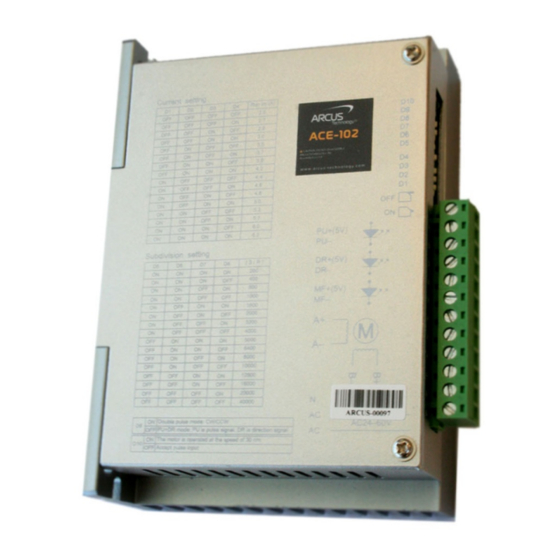
1. Introduction ACE-102 is a high voltage/current microstep driver. It is suitable for motor sizes NEMA 23 and NEMA 34 2-phase bipolar stepper motors. It accepts both DC and AC voltage input. 1.1 Feature Highlights 24 to 80 VDC input 24 to 60 VAC input Max Current: 6.2 A (RMS), 8.7A (Peak) -
Page 5: Dimensions
2. Dimensions Figure 2.0 ACE-102 Manual page 5 rev 1.07... -
Page 6: Connectors
3. Connectors In order for ACE-102 to operate, it must be supplied with +12VDC to +24VDC. Power pins as well as pin outs are shown below. Figure 3.0 3.1. 12 pin Connector Information Pin # Name Description PUL+ Pulse+ (CW+) Opto-isolated Input... -
Page 7: Ace-102 Interface Circuit
3.2. ACE-102 Interface Circuit Figure 3.1 ACE-102 Manual page 7 rev 1.07... -
Page 8: Pulse/Dir/En Inputs
3.3. Pulse/Dir/En Inputs ACE-102 supports both one-clock (Pulse/Dir) or two-clock (CW/CCW) inputs. One-clock uses Pulse signal as the amount of movement and Dir signal as the direction of the movement. Figure 3.2 Two-clock uses CW as clockwise movement and CCW as counter clockwise movement. -
Page 9: Configuration
OFF OFF OFF OFF OFF OFF OFF OFF OFF OFF OFF OFF OFF OFF OFF OFF Table 4.1 4.3. Miscellaneous Settings Dipswitch 2 CLK Mode 1 CLK Mode (CW/CCW) (PUL/DIR) Auto Move On Auto Move (30RPM) Table 4.2 ACE-102 Manual page 9 rev 1.07... - Page 10 Contact Information Arcus Technology, Inc. 3159 Independence Drive Livermore, CA 94551 925-373-8800 www.arcus-technology.com The information in this document is believed to be accurate at the time of publication but is subject to change without notice. ACE-102 Manual page 10 rev 1.07...
Need help?
Do you have a question about the ACE-102 and is the answer not in the manual?
Questions and answers