
Subscribe to Our Youtube Channel
Related Manuals for National Instruments NI PXI-4220


Summary of Contents for National Instruments NI PXI-4220
- Page 1 NI PXI-4220 User Manual NI PXI-4220 User Manual July 2003 Edition Part Number 323530A-01...
- Page 2 Thailand 662 992 7519, United Kingdom 44 0 1635 523545 For further support information, refer to the Signal Conditioning Technical Support Information document. To comment on the documentation, send email to techpubs@ni.com. © 2003 National Instruments Corporation. All rights reserved.
- Page 3 Warranty The NI PXI-4220 is warranted against defects in materials and workmanship for a period of one year from the date of shipment, as evidenced by receipts or other documentation. National Instruments will, at its option, repair or replace equipment that proves to be defective during the warranty period.
- Page 4 Conventions The following conventions are used in this manual: <> Angle brackets that contain numbers separated by an ellipsis represent a range of values associated with a bit or signal name—for example, DIO<3..0>. » The » symbol leads you through nested menu items and dialog box options to a final action.
-
Page 5: Table Of Contents
NI-DAQ......................1-4 Installing the Software ....................1-4 Installing the NI PXI-4220 Hardware................1-4 Unpacking......................1-5 Installing the NI PXI-4220 Device into a PXI Chassis ........1-5 Verifying the Installation ....................1-7 Troubleshooting the Self-Test Verification ..............1-8 Removing the NI PXI-4220 ...................1-8 Removing the PXI-4220 from a PXI Chassis..........1-8 Removing the NI PXI-4220 from MAX ............1-9... - Page 6 Half-Bridge Type II ..................4-11 Full-Bridge Type I ..................4-13 Full-Bridge Type II ..................4-15 Full-Bridge Type III..................4-17 NI PXI-4220 Theory of Operation ................4-19 Bridge Configuration and Completion............4-22 Excitation ......................4-22 Remote Sense ................... 4-23 Gain/Input Range .................... 4-25 Filter ........................
- Page 7 Using a DAQmx Channel Property Node in LabVIEW ....5-10 Synchronization and Triggering ..............5-11 Synchronizing the NI PXI-4220 ..............5-12 Synchronizing the NI PXI-4220 Using LabVIEW ......5-14 Other Application Documentation and Material ............5-15 Calibrating the NI PXI-4220..................5-16 Calibrating the NI PXI-4220 ................5-16 Internal Calibration Procedure ............5-16...
- Page 8 Signal During Simultaneous Sample and Hold Sampling ....4-30 Figure 4-18. AI CONV CLK Signal Routing ............4-33 Figure 4-19. NI PXI-4220 PXI Trigger Bus Signal Connection ....... 4-35 Figure 5-1. Typical Program Flowchart ..............5-2 Figure 5-2. LabVIEW Channel Property Node with Filtering Enabled at 10 kHz and SS/H Disabled ..........
- Page 9 Table 4-4. PXI Trigger Bus Timing Signals............4-35 Table 5-1. NI-DAQmx Properties ................5-4 Table 5-2. Programming a Task in LabVIEW............5-8 Table 5-3. Synchronizing the NI PXI-4220 Using LabVIEW........5-14 Table A-1. Maximum Sampling Rates ..............A-1 © National Instruments Corporation NI PXI-4220 User Manual...
-
Page 10: Installing The Ni Pxi-4220
Installing the NI PXI-4220 The NI PXI-4220 is part of the SC Series of data acquisition (DAQ) devices with integrated signal conditioning. The SC Series reduces measurement set up and configuration complexity by integrating signal conditioning and DAQ on the same product. -
Page 11: What You Need To Get Started
The NI PXI-4220 is configured using Measurement & Automation Explorer (MAX) or through function calls to NI-DAQmx. What You Need to Get Started To set up and use the NI PXI-4220, you need the following: ❑ NI PXI-4220 device ❑... -
Page 12: Software Programs
You can download NI documents from ni.com/manuals Software Programs When programming National Instruments DAQ hardware, you can use an NI application development environment (ADE) or other ADEs. In either case, you use the NI-DAQmx application programming interface (API). National Instruments ADE Software LabVIEW features interactive graphics, a state-of-the-art interface, and a powerful graphical programming language. -
Page 13: Ni-Daq
CD. Note The NI PXI-4220 is not supported in Traditional NI-DAQ. Installing the NI PXI-4220 Hardware This section describes how to install the NI PXI-4220 for use in the PXI chassis. NI PXI-4220 User Manual ni.com... -
Page 14: Unpacking
If you are using the NI PXI-4220 in a PXI-1010 or PXI-1011 combination chassis, Note NI recommends you not install the device into the right-most PXI slot. The NI PXI-4220 cannot control the SCXI chassis slots in a combination chassis. -
Page 15: Figure 1-1. Installing The Ni Pxi-4220 Device
I - 1 0 0 0 1 PXI Chassis 5 Front-Panel Mounting Screws 2 PXI System Controller 6 Guides 3 NI PXI-4220 Module 7 Power Switch 4 Injector/Ejector Handle Figure 1-1. Installing the NI PXI-4220 Device NI PXI-4220 User Manual ni.com... -
Page 16: Verifying The Installation
Verifying the Installation When you power up the computer, the system should automatically detect the NI PXI-4220. You can use MAX to verify that the NI PXI-4220 is installed correctly. To verify the installation and successful detection of the NI PXI-4220, complete the following steps: If you need help during the verification process, open the Measurement &... -
Page 17: Troubleshooting The Self-Test Verification
Chapter 1 Installing the NI PXI-4220 Troubleshooting the Self-Test Verification If the self-test verification did not verify the NI PXI-4220 installation or the NI PXI-4220 did not appear in MAX, complete the following steps to troubleshoot the installation. Check to see if the operating system detected the card. -
Page 18: Removing The Ni Pxi-4220 From Max
Slide the device completely out. The next time you restart the computer the NI PXI-4220 will have a red circle with a white X inside it next to the device in MAX. -
Page 19: Connecting Signals
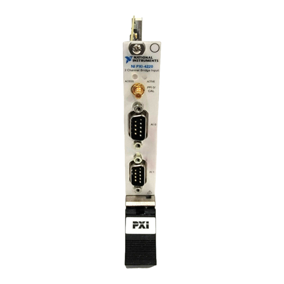
Refer to the Read Me First: Safety and Radio-Frequency Interference document before removing equipment covers or connecting/disconnecting any signal wires. Figure 2-1 shows the NI PXI-4220 front label, including the location of the DSUB connectors and PFI0/CAL SMB connector. © National Instruments Corporation... -
Page 20: Figure 2-1. Ni Pxi-4220 Front Label
The PFI0/CAL SMB connector is for low-voltage timing and calibration signals only. Voltages greater than ±10 V can damage the device. Figure 2-2 shows the pin signal assignments for each of the NI PXI-4220 DSUB connectors. Refer to Figure 2-2 when constructing DSUB connection leads to ensure the signal wires are routed correctly. -
Page 21: Figure 2-2. Ni Pxi-4220 Signal Connector Pin Assignments
Excitation + (P+) Excitation – (P–) Remote Sense + (RS+) Remote Sense – (RS–) Shunt Cal A (SCA) QTR/Shunt Cal B (QTR/SCB) Shunt Cal COM (SCCOM) Figure 2-2. NI PXI-4220 Signal Connector Pin Assignments © National Instruments Corporation NI PXI-4220 User Manual... -
Page 22: Quarter-Bridge Type I
NI recommends using a 0.1% precision resistor. If a less precise resistor is used, offset null compensation calibration is not as accurate. Refer to the Offset Null Compensation section of Chapter 4, Theory of Operation, for more information. NI PXI-4220 User Manual ni.com... -
Page 23: Quarter-Bridge Type Ii
The quarter-bridge type II is often confused with the more commonly used half-bridge type I. For more information, refer to the Quarter-Bridge Type II Half-Bridge Type I sections of Chapter 4, Theory of Operation. © National Instruments Corporation NI PXI-4220 User Manual... -
Page 24: Half-Bridge Type I
Poisson effect (–νε). • is an active element measuring tensile strain (+ε). • is the excitation voltage. • is the lead resistance. • is the voltage measured. • is shunt calibration resistor A. NI PXI-4220 User Manual ni.com... -
Page 25: Half-Bridge Type Ii
(–ε). • is an active element measuring tensile strain (+ε). • is the excitation voltage. • is the lead resistance. • is the voltage measured. • is shunt calibration resistor A. © National Instruments Corporation NI PXI-4220 User Manual... -
Page 26: Full-Bridge Type I
(–ε). • is an active element measuring tensile strain (+ε). • is the excitation voltage. • is the lead resistance. • is the measured voltage. • is shunt calibration resistor A. NI PXI-4220 User Manual ni.com... -
Page 27: Full-Bridge Type Ii
(–ε). • is an active element measuring tensile strain (+ε). • is the excitation voltage. • is the lead resistance. • is the measured voltage. • is shunt calibration resistor A. © National Instruments Corporation NI PXI-4220 User Manual... -
Page 28: Full-Bridge Type Iii
Poisson effect (–νε). • is an active element measuring the tensile strain (+ε). • is the excitation voltage. • is the lead resistance. • is the measured voltage. • is shunt calibration resistor A. NI PXI-4220 User Manual 2-10 ni.com... -
Page 29: Remote Sense
Chapter 2 Connecting Signals Remote Sense For remote sensing, wire the NI PXI-4220 for remote sense as shown in Figure 2-10. Refer to the Remote Sense section of Chapter 4, Theory of Operation, for more information about remote sensing. Using remote sense... -
Page 30: Configuring And Testing
The test panels allow you to measure the signal connected to the NI PXI-4220 directly as well as configure some of the properties of your measurement. To open the NI PXI-4220 device test panels when in MAX,... -
Page 31: Ni Pxi-4220 Software-Configurable Settings
MAX to programmatically perform offset null compensation and shunt calibration. It also describes how to perform configuration of these settings for the NI PXI-4220 in NI-DAQmx. For more information about the relationship between the... -
Page 32: Filter
Gain/input range refers to the signal conditioning gain and digitizer input range, software configurable settings that allow you to choose the appropriate amplification to fully utilize the range of the NI PXI-4220 DAQ circuitry. In most applications NI-DAQ sets the gain for you determined by the input range. -
Page 33: Shunt Calibration Switches
7.0 or later of an NI ADE. You can use MAX to configure your bridge-based sensor measurement. This section describes where you can access each software-configurable setting available in MAX. NI PXI-4220 User Manual ni.com... -
Page 34: Ni-Daqmx
Strain and custom voltage with excitation are the most commonly used NI-DAQmx Task or NI-DAQmx Global Channel types with the NI PXI-4220. Use the Custom Voltage with Excitation NI-DAQmx Task or Global Channel when measuring load, force, torque, pressure or other bridge-based sensors. -
Page 35: Creating A Strain Global Channel Or Task
This leaves the shunt calibration resistor disconnected from the circuit. For more information about how to further configure the NI PXI-4220, or how to use Note LabVIEW to configure the device and take measurements, refer to Chapter 5,... -
Page 36: Creating A Custom Voltage With Excitation Global Channel Or Task
Chapter 3 Configuring and Testing For most NI PXI-4220 applications, you should set the autozero mode to None. Note Autozero is not useful for relative transducers such as strain gauges. Autozero performs a software compensation for offset voltage from the signal conditioning and DAQ circuitry, not the transducer, and is therefore not as accurate as hardware offset null compensation. -
Page 37: Verifying The Signal
Verifying the Signal in NI-DAQmx Using a Task or Global Channel You can verify the signals on the NI PXI-4220 using NI-DAQmx by completing the following steps: Click the + next to Data Neighborhood. - Page 38 You have now verified the NI PXI-4220 configuration and signal connection. Note For more information on how to further configure the NI PXI-4220, or how to use LabVIEW to configure the module and take measurements, refer to Chapter 5, Developing Your Application.
-
Page 39: Theory Of Operation
Wheatstone bridge. The Wheatstone bridge configuration is used to measure the small variations in resistance that the sensing elements produce corresponding to physical changes in the specimen. © National Instruments Corporation NI PXI-4220 User Manual... -
Page 40: Strain Gauges
In the figures and equations in this document, the acronyms, formulas, and variables are defined as: ε is the measured strain (+ε is tensile strain and –ε is compressive strain). ε is the simulated strain. NI PXI-4220 User Manual ni.com... - Page 41 (unstrained) – ------------------------------------------------------------------------------ - © National Instruments Corporation NI PXI-4220 User Manual...
-
Page 42: Software Scaling And Equations
A passive quarter-bridge completion resistor (dummy resistor) is required in addition to half-bridge completion. • Temperature variation in specimen decreases the accuracy of the measurements. Sensitivity at 1000 µε is ∼ 0.5 mV • input. NI PXI-4220 User Manual ni.com... -
Page 43: Figure 4-3. Quarter-Bridge I Circuit Diagram
To minimize temperature drift errors, the strain gauge should have a self-temperature-compensation (STC) number that corresponds to the thermal expansion coefficient of the material under test. STC gauges have © National Instruments Corporation NI PXI-4220 User Manual... -
Page 44: Quarter-Bridge Type Ii
Figure 4-4 shows how to position a strain-gauge resistor in an axial and bending configurations. Figure 4-5 shows the quarter-bridge type II circuit wiring diagram. (+ ) (+ ) Axial Bending Figure 4-4. Quarter-Bridge Type II Measuring Axial and Bending Strain NI PXI-4220 User Manual ni.com... -
Page 45: Figure 4-5. Quarter-Bridge Ii Circuit Diagram
(dummy gauge). • is the active strain-gauge element measuring tensile strain (+ε). • is the excitation voltage. • is the lead resistance. • is the voltage measured. © National Instruments Corporation NI PXI-4220 User Manual... - Page 46 ) of the wiring if shunt calibration is performed or if lead length is very short (∼ <10 ft), depending on the wire gauge. For example, 10 ft of 24-AWG copper wire has a lead resistance of 0.25 Ω. NI PXI-4220 User Manual ni.com...
-
Page 47: Half-Bridge Type I
Figure 4-7. Half-Bridge Type I Circuit Diagram The following symbols apply to the circuit diagram and equations: • and R are half-bridge completion resistors. • is the active strain-gauge element measuring compression from Poisson effect (–νε). © National Instruments Corporation NI PXI-4220 User Manual... - Page 48 ) of the wiring if shunt calibration is performed or if lead length is very short (∼ <10 ft), depending on the wire gauge. For example 10 ft of 24-AWG copper wire has a lead resistance of 0.25 Ω. NI PXI-4220 User Manual 4-10 ni.com...
-
Page 49: Half-Bridge Type Ii
Rejects axial strain. • Compensates for specimen temperature variation. Sensitivity at 1000 µε is ∼ 1 mV • input. (+ ) – – (– ) Figure 4-9. Half-Bridge Type II Circuit Diagram © National Instruments Corporation 4-11 NI PXI-4220 User Manual... - Page 50 SCA (pin 4) and SCCOM (pin 5). Do not directly short SCA (pin 4) or SCCOM (pin 5) inside your connector unless the strain-gauge leads are short and have minimal lead resistance. NI PXI-4220 User Manual 4-12 ni.com...
-
Page 51: Full-Bridge Type I
Compensates for lead resistance. Sensitivity at 1000 µε is ∼ 2.0 mV • input. (– ) (+ ) – – (+ ) (– ) Figure 4-11. Full-Bridge Type I Circuit Diagram © National Instruments Corporation 4-13 NI PXI-4220 User Manual... - Page 52 SCA (pin 4) and SCCOM (pin 5). Do not directly short SCA (pin 4) or SCCOM (pin 5) inside your connector unless the strain-gauge leads are short and have minimal lead resistance. NI PXI-4220 User Manual 4-14 ni.com...
-
Page 53: Full-Bridge Type Ii
Poisson’s ratio of the specimen material. • Compensates for lead resistance. Sensitivity at 1000 µε is ∼ 1.3 mV • input. (– (+ ) – – (– ) Figure 4-13. Full-Bridge Type II Circuit Diagram © National Instruments Corporation 4-15 NI PXI-4220 User Manual... - Page 54 SCA (pin 4) and SCCOM (pin 5). Do not directly short SCA (pin 4) or SCCOM (pin 5) inside your connector unless the strain-gauge leads are short and have minimal lead resistance. NI PXI-4220 User Manual 4-16 ni.com...
-
Page 55: Full-Bridge Type Iii
Poisson’s ratio of the specimen material. • Compensates for lead resistance. Sensitivity at 1000 µε is ∼ 1.3 mV • input (– (+ ) – – (– (+ ) Figure 4-15. Full-Bridge Type III Circuit Diagram © National Instruments Corporation 4-17 NI PXI-4220 User Manual... - Page 56 SCA (pin 4) and SCCOM (pin 5). Do not directly short SCA (pin 4) or SCCOM (pin 5) inside your connector unless the strain-gauge leads are short and have minimal lead resistance. NI PXI-4220 User Manual 4-18 ni.com...
-
Page 57: Ni Pxi-4220 Theory Of Operation
NI PXI-4220 Theory of Operation This section includes a brief overview and a detailed discussion of the circuit features of the module. Refer to Figure 4-16, which is a block diagram of the NI PXI-4220, while reading this section. © National Instruments Corporation 4-19... -
Page 58: Figure 4-16. Block Diagram Of The Ni Pxi-4220
Chapter 4 Theory of Operation Figure 4-16. Block Diagram of the NI PXI-4220 NI PXI-4220 User Manual 4-20 ni.com... - Page 59 1 or 20 gain setting of the instrumentation amplifier, permit the NI PXI-4220 to have 49 gain settings between 1 and 1000. By default the NI PXI-4220 T/H circuitry is enabled to allow SS/H. This allows you to acquire synchronized measurements from both channels.
-
Page 60: Bridge Configuration And Completion
The quarter-bridge completion resistor is socketed for easy replacement. The quarter-bridge completion resistor for AI 0 is located on the NI PXI-4220 at reference designator R5, the completion resistor for AI 1 is located at R2. -
Page 61: Remote Sense
NI recommends connecting the remote sense pins directly to the sensor to obtain Note optimum excitation voltage regulation and measurement accuracy. © National Instruments Corporation 4-23 NI PXI-4220 User Manual... - Page 62 Theory of Operation The NI PXI-4220 excitation output circuits set the output voltage by monitoring the remote sense pins. Hence, the NI PXI-4220 corrects for a voltage (I × R) drop in the excitation leads between the module and the bridge, even if lead resistance changes with temperature.
-
Page 63: Gain/Input Range
Theory of Operation Gain/Input Range In normal NI PXI-4220 operation you do not need to set the gain. NI-DAQmx automatically sets the appropriate gain based on the range of your task or global channel, or the input limits set in LabVIEW. -
Page 64: Filter
For example, since the NI PXI-4220 DAQ circuitry has a maximum analog input range of ±10 V and you have set the maximum input to the NI PXI-4220 to be +12 mV, set the gain to the setting closest to 10 V... -
Page 65: Offset Null Compensation
Theory of Operation Offset Null Compensation The NI PXI-4220 provides offset null compensation to adjust signal voltages to proper levels when the strain gauge or bridge sensor is at rest (unstrained). For most sensors offset null compensation is used to remove an initial voltage offset from the Wheatstone bridge. -
Page 66: Shunt Calibration
SCA (pin 4), QTR/SCB (pin 9), and SCCOM (pin 5) on the DSUB connectors. Each shunt calibration circuit consists of a resistor in series with a switch. The NI PXI-4220 shunt calibration switch is a long-life solid-state switch. The electronic switch is galvanically isolated from ground;... -
Page 67: Simultaneous Sample And Hold
T/H circuitry. The outputs of the T/H amplifiers follow their inputs, also called tracking the inputs, until they receive a hold signal from the DAQ circuitry. Both channels on the NI PXI-4220 hold their signal at the same time. Multiple NI PXI-4220 devices can be synchronized, allowing you to simultaneously sample channels on multiple modules. -
Page 68: Figure 4-17. Signal During Simultaneous Sample And Hold Sampling
It is possible to enable and disable SS/H programmatically in NI-DAQmx, although NI recommends that you leave SS/H enabled for most applications. By default the NI PXI-4220 has SS/H enabled. You should only disable SS/H if your application does not require simultaneous... -
Page 69: Maximum Acquisition Rate
50 or 60 Hz powerline noise. The minimum NI PXI-4220 CMRR is 85 dB at gains ≥20. This results in 0.006% of the CMV introduced as error on the measured signal. -
Page 70: Effective Cmr
Timing and Control Functional Overview The NI PXI-4220 is similar to the NI E Series DAQ device architecture in many ways. This architecture uses the NI data acquisition system timing controller (DAQ-STC) for time-related functions. The DAQ-STC consists of two timing groups that control AI and general-purpose counter/timer functions. -
Page 71: Programmable Function Inputs
(SI2) counter TC. Programmable Function Inputs PFI0 is connected to the front SMB connector of the NI PXI-4220. Software can select PFI0 as the external source for a given timing signal. Any timing signal can use the PFI0 pin as an input, and multiple timing signals can simultaneously use the same PFI. -
Page 72: Device And Pxi Clocks
A/D conversions, digital-to-analog converter (DAC) updates, or general-purpose signals at the I/O connector. The NI PXI-4220 can use either its internal 20 MHz master timebase or an external timebase received over the PXI trigger bus on the PXI clock line. -
Page 73: Figure 4-19. Ni Pxi-4220 Pxi Trigger Bus Signal Connection
PXI Trigger<7> Switch Master Timebase Figure 4-19. NI PXI-4220 PXI Trigger Bus Signal Connection Table 4-4 provides more information about each of the timing signals available on the PXI trigger bus. For more detailed timing signal information, refer to Appendix B, Timing Signal Information. - Page 74 Output AI PAUSE TRIG Input This signal can pause and resume Input Input acquisition. AI SAMPLE CLK Input This timebase provides the master clock Input Input TIMEBASE from which the sample clocks are derived. NI PXI-4220 User Manual 4-36 ni.com...
-
Page 75: Developing Your Application
Developing Your Application This chapter describes basic programming information for the NI PXI-4220 and how to develop your application in LabVIEW. Developing Your Application in NI-DAQmx If you are not using an NI ADE, using an NI ADE prior to version 7.0, or using an... -
Page 76: Figure 5-1. Typical Program Flowchart
Perform Offset Bridge Null Null Compensation? Operation Process Data Perform Shunt Display Data? Calibration? Graphical Shunt Calibration Display Tools Operation Continue Sampling? Start Measurement Read Measurement Stop Measurement Clear Task Figure 5-1. Typical Program Flowchart NI PXI-4220 User Manual ni.com... -
Page 77: General Discussion Of Typical Flow Chart
Refer to the Synchronizing the NI PXI-4220 section for more information about synchronizing multiple NI PXI-4220 devices. Programmatically adjusting properties for a task created in the DAQ Assistant overrides the original, or default, settings only for that session. -
Page 78: Adjusting Timing And Triggering
Configuring Channel Properties All of the different ADEs used to configure the NI PXI-4220 access an underlying set of NI-DAQmx properties. Table 5-1 is a list of some of the properties that configure the NI PXI-4220. - Page 79 Nominal Resistance Analog Input»Strain»Strain Specifies the sensitivity AI.StrainGage.GageFactor Gage»Gage Factor of the strain gauge. Analog Input»Strain»Strain Specifies the ratio of AI.StrainGage.PoissonRatio Gage»Poisson Ration lateral strain to axial strain in the specimen material. © National Instruments Corporation NI PXI-4220 User Manual...
-
Page 80: Perform Offset Null Compensation
ADE Help. Perform Offset Null Compensation The NI PXI-4220 provides offset null compensation circuitry to adjust signal voltages to proper levels when the strain gauge or bridge sensor is at rest (unstrained). For most sensors offset null compensation is used to remove an initial voltage offset from the Wheatstone bridge. -
Page 81: Perform Shunt Calibration
Some custom scaling applications require the actual excitation voltage applied to the bridge instead of the nominal excitation voltage output by the NI PXI-4220. You can scan the remote sense pins RSX+ (pin 3) and RSX– (pin 8) with the DAQmx physical channels DevX/_pPosX to find the actual excitation voltage. -
Page 82: Completing The Application
This section describes in more detail the steps shown in the typical program flowchart in Figure 5-1, such as how to create a task in LabVIEW and configure the channels of the NI PXI-4220. If you need more information or for further instructions, select Help»VI, Function, & How-To Help from the LabVIEW menu bar. - Page 83 Analyze Data Some examples of data analysis include filtering, scaling, harmonic analysis, or level checking. Some data analysis tools are located on the Functions»Signal Analysis subpalette and on the Functions»All Functions»Analyze subpalette. © National Instruments Corporation NI PXI-4220 User Manual...
-
Page 84: Using A Daqmx Channel Property Node In Labview
Clear Task DAQmx Clear Task.vi Using a DAQmx Channel Property Node in LabVIEW With the NI PXI-4220 you must use property nodes to disable SS/H. Note You can use property nodes in LabVIEW to manually configure your channels. To create a LabVIEW property node, complete the following steps: Launch LabVIEW. -
Page 85: Synchronization And Triggering
NI-DAQmx properties. Synchronization and Triggering If you have multiple NI PXI-4220 devices, you can synchronize them to acquire samples at the same time and at the same rate. With SS/H enabled, and each device synchronized, you can use multiple NI PXI-4220 devices to acquire and analyze complex signals. -
Page 86: Synchronizing The Ni Pxi-4220
Chapter 5 Developing Your Application The NI PXI-4220 that generates the start trigger and the timebase for all of the synchronized devices is called the master. The master NI PXI-4220 exports the shared timing signals through the PXI bus to the slave devices. -
Page 87: Figure 5-3. General Synchronizing Flowchart
Start Master Measurement Create a Slave Task Create Slave Read Measurement Channels Configure Slave Channel Continue Sampling? More Slave Tasks? Clear Master Task, Clear Slave Task Figure 5-3. General Synchronizing Flowchart © National Instruments Corporation 5-13 NI PXI-4220 User Manual... -
Page 88: Synchronizing The Ni Pxi-4220 Using Labview
Except where otherwise stated, the VIs in Table 5-3 are located on the Functions» All Functions»NI Measurements»DAQmx - Data Acquisition subpalette and accompanying subpalettes in LabVIEW. Table 5-3. Synchronizing the NI PXI-4220 Using LabVIEW Flowchart Step VI or Program Step Create a Master Task —This VI is optional if you created... -
Page 89: Other Application Documentation And Material
• LabVIEW Example Programs, available by selecting Open» Examples from the opening screen. Most of the examples applicable to the NI PXI-4220 are located in Hardware Input and Output» DAQmx»Analog Measurements and Hardware Input and Output»DAQmx»Synchronization»Multi-Device. Note The example program , located Acq Strain Samples (with Calibration).vi... -
Page 90: Calibrating The Ni Pxi-4220
System calibration removes the offset and gain errors, two sources of potential measurement errors. Calibrating the NI PXI-4220 The NI PXI-4220 is shipped with a calibration certificate and is calibrated at the factory to the specifications described in Appendix A, Specifications. Calibration constants are stored on the NI PXI-4220. -
Page 91: External Device Calibration
NI recommends you perform an external calibration once a year. At the time of publication, there is currently no external calibration procedure document available for the NI PXI-4220. Return the NI PXI-4220 to NI for external calibration. NI provides a certificate of calibration with the calibrated NI PXI-4220. -
Page 92: Table 4-3. Maximum Sampling Rates
Specifications This appendix lists the specifications for the NI PXI-4220 device. These specifications are typical at 25 °C unless otherwise noted. All specifications are with SS/H enabled unless otherwise noted. Analog Input Number of input channels ...... 2 Voltage gain settings......X1 to X1000 with the following gain settings: 1;... -
Page 93: Appendix A Specifications
Appendix A Specifications NI PXI-4220 Accuracy Information Absolute Accuracy Noise + Quantization Temperature Drift µ Offset Absolute Nominal % of Reading Maximum Single Gain Drift Drift Accuracy at µ µ Range Gain 1 Year Offset ( Averaged (%/°C) /°C) Full Scale ±10.0 V... - Page 94 Recommended warm-up time ....15 minutes External calibration interval....1 year Onboard calibration reference Level ..........5.000 V ±1 mV (actual value stored in EEPROM) Temperature coefficient ....±0.6 ppm/°C Long-term stability ......6 ppm/ 1,000 h © National Instruments Corporation NI PXI-4220 User Manual...
- Page 95 Lowpass filter settings ......10 Hz, 100 Hz, 1 kHz, 10 kHz, or bypass Bandwidth, filter bypassed .....–3 db at 20 kHz The pre-calibration errors apply only for users doing register level programming. NI-DAQmx users do not see the pre-calibration errors. NI PXI-4220 User Manual ni.com...
- Page 96 Settings........... 0.0 to 10.0 V in 1024 equally spaced increments Error ............±20 mV ±0.3% of nominal setting. ±0.1% of value read from remote sense Maximum operating current....29 mA, all ranges Short-circuit protection ......Yes © National Instruments Corporation NI PXI-4220 User Manual...
- Page 97 Shunt calibration resistors are located near the front of the PXI-4220 and are socketed. Resistors shipped with the PXI-4220 are 100 kΩ RN-55 style (standard 1/4 W size). The tolerance is ±0.1% and the temperature coefficient is 10 ppm/°C max. NI PXI-4220 User Manual ni.com...
- Page 98 Power requirements........ 1 A at ±5 VDC (±5%) Physical Dimensions (not including connectors) ..... 16.0 by 10.0 by 2.0 cm (6.3 by 3.9 by 0.79 in.) Analog input signal connector ....9-pin DSUB © National Instruments Corporation NI PXI-4220 User Manual...
- Page 99 Relative humidity ........10 to 90%, non-condensing Maximum altitude........2,000 m Pollution Degree (indoor use only) ..2 Safety The NI PXI-4220 is designed to meet the requirements of the following standards of safety for electrical equipment for measurement, control, and laboratory use: •...
- Page 100 Appendix A Specifications CE Compliance The NI PXI-4220 meets the essential requirements of applicable European Directives, as amended for CE marking, as follows: Low-Voltage Directive (safety) ..... 73/23/EEC Electromagnetic Compatibility Directive (EMC) ........89/336/EEC Note Refer to the Declaration of Conformity (DoC) for this product for any additional regulatory compliance information.
- Page 101 In level-detection mode, there are no pulse width requirements imposed by the PFIs themselves. Limits can be imposed by the particular timing signal being controlled. These requirements are listed in the sections describing the particular signals. © National Instruments Corporation NI PXI-4220 User Manual...
-
Page 102: Typical Posttriggered Sequence
Figure B-2 shows a typical pretriggered sequence. AI START TRIG AI REF TRIG AI SAMP CLK AI CONV CLK Scan Counter Figure B-2. Typical Pretriggered Sequence NI PXI-4220 User Manual ni.com... -
Page 103: Ai Start Trig Input Signal Timing
The device also uses AI START TRIG to initiate pretriggered operations. In pretriggered applications, AI START TRIG is generated by a software trigger unless a PFI pin is selected as the source of AI START TRIG. Refer © National Instruments Corporation NI PXI-4220 User Manual... -
Page 104: Ai Ref Trig Input Signal Timing
50 to 100 ns. This output is set to high-impedance at startup. Figures B-5 and B-6 show the input and output timing requirements for AI REF TRIG. Rising-Edge Polarity Falling-Edge Polarity = 10 ns minimum Figure B-5. AI REF TRIG Input Signal Timing NI PXI-4220 User Manual ni.com... - Page 105 , after the last conversion in the scan is initiated. This output is set to high-impedance at startup. Figures B-7 and B-8 show the input and output timing requirements for AI SAMP CLK. © National Instruments Corporation NI PXI-4220 User Manual...
-
Page 106: Ai Samp Clk Input Signal Timing
AI CONV CLK appears when the onboard SI2 counter reaches zero. If you select an external AI CONV CLK, the first external pulse after AI SAMP CLK generates a conversion. Separate the AI SAMP CLK pulses by at least one scan period. NI PXI-4220 User Manual ni.com... -
Page 107: Ai Conv Clk Input Signal Timing
100 ns. This output is set to high-impedance at startup. Figures B-9 and B-10 show the input and output timing requirements for AI CONV CLK. Rising-Edge Polarity Falling-Edge Polarity = 10 ns minimum Figure B-9. AI CONV CLK Input Signal Timing © National Instruments Corporation NI PXI-4220 User Manual... - Page 108 Separate the AI CONV CLK pulses by at least one conversion period. The NI PXI-4220 sample interval counter generates AI CONV CLK unless you select an external source. The AI SAMP CLK signal starts the counter, which counts down and reloads itself until the scan finishes.
- Page 109 This signal has a 400 to 500 ns pulse width and is software enabled. Figure B-12 shows the timing for AI HOLD COMPLETE. © National Instruments Corporation NI PXI-4220 User Manual...
- Page 110 The polarity of AI HOLD COMPLETE is not software selectable when Note programmed using NI-DAQmx. It is a positive polarity pulse. AI CONV CLK AI HOLD COMPLETE = 50 to 100 ns = 400 to 500 ns Figure B-12. AI HOLD COMPLETE Signal Timing NI PXI-4220 User Manual B-10 ni.com...
- Page 111 This appendix lists common questions related to the use of the NI PXI-4220. Which version of NI-DAQ works with the NI PXI-4220 and how do I get the most current version of NI-DAQ? You must have NI-DAQ 7.0 or later and use NI-DAQmx. Visit ni.com...
- Page 112 NI PXI-4220. If I am powering my bridge-based transducers with an external voltage source, what voltage setting should I set on the NI PXI-4220? Even with an external voltage source for the transducers, internal excitation voltage is still used by the offset null compensation circuitry inside the NI PXI-4220.
- Page 113 – negative of, or minus ° degree Ω amperes analog-to-digital alternating current analog-to-digital converter—an electronic device, often an integrated circuit, that converts an analog voltage to a digital number © National Instruments Corporation NI PXI-4220 User Manual...
- Page 114 Typically, a bus is the expansion vehicle to which I/O or other devices are connected. bus master a type of a plug-in device or controller with the ability to read and write devices on the computer bus Celsius CalDAC calibration DAC NI PXI-4220 User Manual ni.com...
- Page 115 D/A and/or DIO devices in the same computer DAQ Assistant a configuration utility with which you define and configure your DAQ operation DAQ-STC data acquisition system timing controller chip © National Instruments Corporation NI PXI-4220 User Manual...
- Page 116 NI PXI-4220 User Manual ni.com...
- Page 117 A/D or D/A transfer characteristic of the analog I/O circuitry input bias current the current that flows into the inputs of a circuit input impedance the resistance and capacitance between the input terminals of a circuit © National Instruments Corporation NI PXI-4220 User Manual...
- Page 118 Includes both the signal and common-mode voltages. NI PXI-4220 User Manual ni.com...
- Page 119 (NRSE) measurement system reference, but the voltage at this reference can vary with respect to the measurement system ground. output pin—a counter output pin where the counter can generate various TTL pulse waveforms © National Instruments Corporation NI PXI-4220 User Manual...
- Page 120 10 and 90% points of the step response of a system root mean square—the square root of the average value of the square of the instantaneous signal amplitude; a measure of signal amplitude NI PXI-4220 User Manual ni.com...
- Page 121 DAQ SS/H simultaneous sample-and-hold system timing controller © National Instruments Corporation NI PXI-4220 User Manual...
- Page 122 WFTRIG waveform generation trigger signal NI PXI-4220 User Manual G-10 ni.com...
- Page 123 3-2 filter bandwidth, 3-3 filters gain, 3-3, 4-25 bandwidth configuration, 3-3 null potentiometers, 3-3 questions about, C-1 conventions used in the manual, iv full-bridge configuration I, 2-8, 4-13 © National Instruments Corporation NI PXI-4220 User Manual...
- Page 124 I, 2-8, 4-13 full-bridge configuration II, 2-9, 4-15 quarter-bridge configuration I, 2-4, 4-4 full-bridge configuration III, 2-10, 4-17 quarter-bridge configuration II, 2-5, 4-6 half-bridge configuration I, 2-6, 4-9 questions and answers, C-1 half-bridge configuration II, 2-7, 4-11 NI PXI-4220 User Manual ni.com...
- Page 125 SISOURCE signal, B-9 DAQ timing connections, B-2 STARTSCAN signal, B-5 programmable function input TRIG1 signal, B-3 connections, B-1 TRIG2 signal, B-4 SISOURCE signal, B-9 typical posttriggered acquisition software (figure), B-2 NI-DAQ version required, C-1 © National Instruments Corporation NI PXI-4220 User Manual...
- Page 126 CONVERT* signal routing (figure), 4-33 device and RTSI clocks, 4-34 programmable function inputs, 4-33 TRIG1 signal, B-3 See also PFI0/TRIG1 signal TRIG2 signal, B-4 See also PFI1/TRIG2 signal troubleshooting, questions and answers, C-1 NI PXI-4220 User Manual ni.com...
Need help?
Do you have a question about the NI PXI-4220 and is the answer not in the manual?
Questions and answers