Table of Contents
Advertisement
Quick Links
Advertisement
Table of Contents

Subscribe to Our Youtube Channel
Related Manuals for Sonel LKZ-1500


Summary of Contents for Sonel LKZ-1500
- Page 3 USER MANUAL CABLES AND UNDERGROUND INFRASTRUCTURE LOCATOR LKZ-1500-LITE LKZ-1500 SONEL S.A. Wokulskiego 11 58-100 Świdnica Version 2.00 12.10.2021...
- Page 4 Locator LKZ-1500 is a modern, high quality measuring device, easy and safe to use. Reading and us- ing of this manual will help to avoid errors in measurements and prevent possible problems when op- erating the instrument. LKZ-1500-LITE ● LKZ-1500 – USER MANUAL...
-
Page 5: Table Of Contents
Fault finding with insulation control sensors – DKI-E or A-frame ....37 5.2.1 Insulation fault finding by signal drop ................38 5.2.2 The search of the insulation failure by the signal rise ............39 5.2.3 Cable breakdown location ....................40 LKZ-1500-LITE ● LKZ-1500 – USER MANUAL... - Page 6 12.2.1 Basic technical data ......................50 12.2.2 Other technical data ......................51 13 Accessories ....................52 13.1 Standard accessories ..................... 52 13.2 Optional accessories ....................52 14 Service ......................53 15 Laboratory services ..................54 LKZ-1500-LITE ● LKZ-1500 – USER MANUAL...
-
Page 7: Safety
The LKZ-1500 kit can only be used by qualified persons with the required electrical work permit. Using the kit by unauthorized persons may damage the device and cause serious danger to the user. -
Page 8: Description Of The System
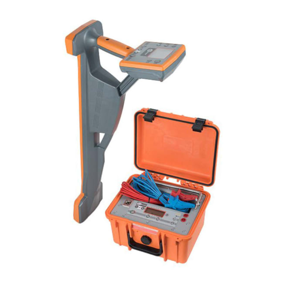
Description of the system The LKZ-1500 locator system consists of an LKO-1500 receiver and an LKN-1500 transmitter kitted as follows: LKZ-1500-LITE is a kit of LKN-1500 with LKO-1500-LITE; LKZ-1500 is a kit of LKN-1500 with LKO-1500. The system allows to track a route of the underground objects like: ... -
Page 9: Operating Principle Of The Transmitter Lkn-1500
The transmitter operation and status infor- mation is presented on front panel display. Design and front panel of the transmitter Fig. 1 Design of the LKN-1500 transmitter Fig. 2 Front panel of LKN-1500 transmitter LKZ-1500-LITE ● LKZ-1500 – USER MANUAL... -
Page 10: Safety Measures
During operation prevent moisture getting into the transmitter panel and/or power supply unit and use it in accordance with the instruction manual. Do not expose to direct sunlight in summer season in order to avoid transmitter over- heating. LKZ-1500-LITE ● LKZ-1500 – USER MANUAL... -
Page 11: Operating The Transmitter
The voltage of the external power supply is below 10.5 V. After 1 minute the Pulsing flashing transmitter will be automatically switched off. Moving from top to Accumulator charges. bottom p. 17 Constant lighting of Accumulator charged. all three icons LKZ-1500-LITE ● LKZ-1500 – USER MANUAL... -
Page 12: Direct Connection - Galvanic Mode
1024 → 8928 → 33k → 273, etc. (see position 1 in Fig. 2). key with an indicator ↑↓ for double frequency 1024 [Hz] Double frequency signal is made by the and φ for double frequency 8928 [Hz]. LKZ-1500-LITE ● LKZ-1500 – USER MANUAL... -
Page 13: Signal Power Output Settings
Also the transmitter power consumption is reduced. Generation modes from continuous to pulsing are switched by pressing the button and dis- played in time with output signal (the green diode is green) by indicator (pos. 12 Fig. 2). LKZ-1500-LITE ● LKZ-1500 – USER MANUAL... -
Page 14: Voltage Output Limitation
(Fig. 5). Fig. 5 Induction current excitation in the localized object For operation from internal inductor press the button . Symbol will be displayed. The inductor reaches its maximum performance at 33 kHz. LKZ-1500-LITE ● LKZ-1500 – USER MANUAL... -
Page 15: Inductive Clamps
H with the load socket (p.13 Fig. 2). Grasp communication line with clamp (Fig. 6). On the transmitter panel press the key to set the frequency from available. Fig. 6 Induction of excitation voltage in localized object with transmitting clamp LKZ-1500-LITE ● LKZ-1500 – USER MANUAL... -
Page 16: Lko-1500-Lite / Lko-1500
Then the signal levels are displayed in a form of line bars and digital values in dB or Volts. The indication may be supported with the audible signal. Design and front panel of the receiver Fig. 7 Design and identification of receiver sockets LKZ-1500-LITE ● LKZ-1500 – USER MANUAL... - Page 17 A removable sun-protective cover can be installed by securing its two Velcro straps by the receiv- er’s handle for easier operation in sunlight. Fig. 8 Receiver with sun–protective cover Fig. 9. LKO-1500-LITE receiver panel LKZ-1500-LITE ● LKZ-1500 – USER MANUAL...
- Page 18 Fig. 10. LKO-1500 receiver panel LKZ-1500-LITE ● LKZ-1500 – USER MANUAL...
- Page 19 TRACE and SENSOR channels in the TRACE-SENSOR mode Enabled locating mode icons: Sharp Peak Broad Peak Null Input signal strength bar graph Test object current Input signal limit violation icon Battery charge icon LKZ-1500-LITE ● LKZ-1500 – USER MANUAL...
-
Page 20: Operating The Receiver
The menu is navigated with buttons . The options may be selected and changed with the button. Fig. 11. Main menu The Indication submenu lists the following options. Fig. 12 Menu “Indication” in LKO-1500 LKZ-1500-LITE ● LKZ-1500 – USER MANUAL... - Page 21 In "Track" mode, the sound reproduces the "peak" signal level. When "Maximum scale" is turned off, sound reproduces the "minimum" scale signal level. In "TRACE SENSOR" mode, the sound re- produces the signal level at the input of the "SENSOR" socket. LKZ-1500-LITE ● LKZ-1500 – USER MANUAL...
- Page 22 Distance – from the last point or from the beginning. Time Zone – time zones in the world. Set from -13 to 13. In the Language submenu – select the language with the buttons Fig. 18. Menu „Language” LKZ-1500-LITE ● LKZ-1500 – USER MANUAL...
-
Page 23: Operating Modes Of The Receiver
Fig. 22. Display with compass in „Track- SENSOR” mode The indicator of the input signal strength in dB (for locating by peak and null) turns red when the corresponding input channels are overloaded (See Pos. 13, Pos. 8 Fig. 19). LKZ-1500-LITE ● LKZ-1500 – USER MANUAL... - Page 24 Input signal from the lower magnetic antenna in dB. Locating is by the peak method (see sec. 4.6.2.1) Volume indicator GPS state, (see sec. 6.2) Logging to the track, displayed at the moment of recording (see sec. 6.2) Battery status icon Receiver axis Utility position arrow Distance (see sec. 6.2.4) LKZ-1500-LITE ● LKZ-1500 – USER MANUAL...
-
Page 25: Locating Methods
– two horizontal antennas operate In the null locating mode, the receiver operates the following: the horizontal antenna; the lower horizontal antenna and the vertical antenna. COMPASS LINE mode requires all 4 antennas of the Receiver. LKZ-1500-LITE ● LKZ-1500 – USER MANUAL... -
Page 26: Peak Mode
Fig. 23 shows the relationship between the signal level and antenna displacement from the utility. Fig. 23 The level of the responding signal depending on the Receiver displacement from the utility axis LKZ-1500-LITE ● LKZ-1500 – USER MANUAL... -
Page 27: Peak Search With 1:4 Scale
The gain-up button is expands the scale. The gain-down button makes the scale shorter. The optimum gain and scale for a specific signal intensity may be obtained by pressing the button. LKZ-1500-LITE ● LKZ-1500 – USER MANUAL... -
Page 28: The Null Method
Utility line Fig. 24. Signal strength change when the receiver moves perpendicularly away from the utility line With the Compass Line enabled, the Null scale is not displayed and cannot be enabled. LKZ-1500-LITE ● LKZ-1500 – USER MANUAL... -
Page 29: Locating With "Compass Line" Option
The utility position arrow may become fuzzy during location. This may occur when the Receiver is perpendicular to the path of the utility line or the Receiver and target utility are distant, or locating sig- nal is too weak. LKZ-1500-LITE ● LKZ-1500 – USER MANUAL... - Page 30 Fig. 25 Locating with “Compass line” LKZ-1500-LITE ● LKZ-1500 – USER MANUAL...
-
Page 31: Locating By Current Direction
In case the adjacent utility lines are galvanically coupled with the target line, all these lines will have the signals of equal direction (See Fig. 27). Signal amplitudes of the adjacent lines may differ depending on the search current spreading. LKZ-1500-LITE ● LKZ-1500 – USER MANUAL... -
Page 32: Depth And Current Intensity Of The Utilities
Receiver before operation to ensure against errors. Track The arrows on the enclosure are in perpendicular to the track centreline Communication Fig. 28 Direct location of the utility depth LKZ-1500-LITE ● LKZ-1500 – USER MANUAL... -
Page 33: Measurement Of Depth
(which is evident by the display message “Weak field” or ---). In these cir- cumstances, it is recommended to determine the depth of the utility with the -6dB method (see Sec- tion. 4.6.3.3). LKZ-1500-LITE ● LKZ-1500 – USER MANUAL... -
Page 34: Indirect 6 Db Test Method For Depth Measurement
Moving to the left and to the right of the utility axis, find the positions in which the readings will be 6 dB less (this means that the signal strength is two times less). The distance between these two points will be equal to double distance from the Receiver to the utility line axis. LKZ-1500-LITE ● LKZ-1500 – USER MANUAL... -
Page 35: Locating By The Utility Current
The first Kirchhoff’s law says that the total current inflowing in a junction is equal to the total outflowing current. You should note, however, that values of the current intensity near the branches will differ from the actual values. Accurate and true measurements may be performed within long-distance and uniform areas only. LKZ-1500-LITE ● LKZ-1500 – USER MANUAL... -
Page 36: Testing Of Ground Plots
Fig. 31 Testing of ground plots without the LKN Transmitter If you are locating a single utility line in the area and with a strong signal, it is recommended to enable Compass line to facilitate tracking (Section 4.6.2.4). LKZ-1500-LITE ● LKZ-1500 – USER MANUAL... -
Page 37: Testing Of Ground Plots With Lkn Transmitter
If the targeted utility line is alone and conducts a strong signal, it is recommended to enable Compass line to facilitate tracking (Section 4.6.2.4). Fig. 32 Ground plot location with the Transmitter in inductive mode LKZ-1500-LITE ● LKZ-1500 – USER MANUAL... -
Page 38: Two-Man Test Method
If the targeted utility line carries a strong signal, it is recommended to enable Compass Line to facilitate tracking (Section 4.6.2.4). Fig. 33 Testing of ground plots without the LKN-1500 Transmitter Repeat the survey in the same way, by moving in perpendicular to the previous direction. LKZ-1500-LITE ● LKZ-1500 – USER MANUAL... -
Page 39: Methods Of Locating Damaged Pipelines And Utilities
The gain may be selected with the gain up/down arrows. For the automatic gain selection use the but- ton. NOTE! Do not supply the voltage of more than 42 V to the SENSOR jack inputs. LKZ-1500-LITE ● LKZ-1500 – USER MANUAL... -
Page 40: Insulation Fault Finding By Signal Drop
(from "+" to "-" or vice versa). In case the insulation is damaged in one point only, the signal level over the damaged point will have a sharp null. Keep in mind that the polarity inversion without a specific signal fluctuation may not be considered as a sign of fault. LKZ-1500-LITE ● LKZ-1500 – USER MANUAL... -
Page 41: The Search Of The Insulation Failure By The Signal Rise
Each operator holds a contact electrode of the sensor during operation. If tracing is per- formed close to the fault, the distance between the operators shall be reduced to clarify the position of cable failure. LKZ-1500-LITE ● LKZ-1500 – USER MANUAL... -
Page 42: Cable Breakdown Location
Shield Short the conductors Conductor A to shield shorting Disconnect Signal strength the ground Fig. 37 Layout and signal strength of tracing of conductor– armor short-circuit LKZ-1500-LITE ● LKZ-1500 – USER MANUAL... -
Page 43: Tracing Of Damaged Insulation And Grounding Area
Fig. 38 Connecting diagram and signal strength for the method of insulation damage tracing with insulation control LKN-1500 Earth fault location Ground Fig. 39 Connecting diagram and phase shift at the phase method of cable insulation failure locating LKZ-1500-LITE ● LKZ-1500 – USER MANUAL... -
Page 44: Data Storage, Gps Navigation
If a wired GPS receiver is used which provides a high accuracy of readings, it is essen- tial for the device to output data compliant with the NMEA-0183 RMC and GGA formats and a 1 Hz refresh rate. LKZ-1500-LITE ● LKZ-1500 – USER MANUAL... -
Page 45: Adjustment Of The Receiver To The Gps Modules
GPS model and quantity of available satellites, and it may last up to 20 minutes. At that, the icon will be shown in yellow. With the next start of the module establishing the connection to the satellites will not exceed a few seconds. LKZ-1500-LITE ● LKZ-1500 – USER MANUAL... -
Page 46: Track Recording
! in the At- tachment field. Fig. 43 Auto save selection display. The Receiver does not store the interval settings in the autonomous memory. They shall be set each time, if necessary, after the Receiver . LKZ-1500-LITE ● LKZ-1500 – USER MANUAL... -
Page 47: Log
“OpenStreetMap”. In this case you shall have Internet connection. If the Internet access is via the proxy-server, you shall adjust the parameters through the LKZ Terminal program settings. In case of poor connection to the network, the map will not be displayed; the other functions will be available. LKZ-1500-LITE ● LKZ-1500 – USER MANUAL... -
Page 48: Power Supply
If completely drained, the battery pack will take 6 to 8 hours to recharge. During prolonged storage of the Receiver, it is recommended to recharge the battery pack every three months. LKZ-1500-LITE ● LKZ-1500 – USER MANUAL... -
Page 49: Possible Faults And Troubleshooting
The headphones show evidence of Repair or replace the headphones. cracking. The headphones fail to deliver sound whereas the sound is good Break in headphone circuit Repair or replace headphones through the internal speakers LKZ-1500-LITE ● LKZ-1500 – USER MANUAL... -
Page 50: Maintenance And Running Repairs
Maintenance and running repairs The service of LKZ-1500 Transmitter and Receiver is about following the rules of operation, stor- age, charging of batteries, routine check and troubleshooting recommended by SONEL S.A. Repair and also replacement of the rechargeable battery or batteries, is allowed only at the manu- facturer factory, or in special repair shops. -
Page 51: Technical Data
50 Hz, V Insulation resistance between “Output” sockets and enclosure (voltage 2500 V) in normal conditions, min- At the voltage 2500 [V] imum, МΩ Notes: m.v.– measured value digits – last digit weight LKZ-1500-LITE ● LKZ-1500 – USER MANUAL... -
Page 52: Other Technical Data
Min. dynamic response range of input signals [dB] Max. bandwidth for specific operating -3 [dB] -60 [dB] -3 [dB] -60 [dB] frequencies [Hz] Utility feature depth measurement [m] 0.10 to 6.00 0.10 to 10.00 LKZ-1500-LITE ● LKZ-1500 – USER MANUAL... -
Page 53: Other Technical Data
▪ LKO-1500 ........................ca. 1.8 kg e) operating temperature ....................-20...+55C storage temperature ...................... -50...+70C g) relative humidity....................max. 95% at +30ºС h) atmospheric pressure ..................from 600 to 1067 hPa fiducial temperature ......................+23 ± 2C LKZ-1500-LITE ● LKZ-1500 – USER MANUAL... -
Page 54: Accessories
A-frame WAADALKZRA2 DKI probe WASONDKI GPS module GT-750 WAADAGT750 N-1 transmitting clamps (Φ=52 mm) WACEGN1BB N-4 transmitting clamps (Φ=110 mm) WACEGN4 N-5 transmitting clamps (Φ=125 mm) WACEGN5 LKZ-1500-LITE ● LKZ-1500 – USER MANUAL... -
Page 55: Service
The manufacturer of the device provides all warranty and after-warranty repairs: SONEL S.A. Wokulskiego 11 58-100 Świdnica Poland tel. +48 74 858 38 60 fax +48 74 858 38 09 E-mail: export@sonel.pl Web page: www.sonel.pl LKZ-1500-LITE ● LKZ-1500 – USER MANUAL... -
Page 56: Laboratory Services
National Metrological Institute. According to ILAC-G24 „Guidelines for determination of calibration intervals of measuring instru- ments”, SONEL S.A. recommends periodical metrological inspection of the instruments it manufac- tures no less frequently than once every 12 months. - Page 57 NOTES LKZ-1500-LITE ● LKZ-1500 – USER MANUAL...
- Page 58 NOTES LKZ-1500-LITE ● LKZ-1500 – USER MANUAL...
Need help?
Do you have a question about the LKZ-1500 and is the answer not in the manual?
Questions and answers