Table of Contents
Advertisement
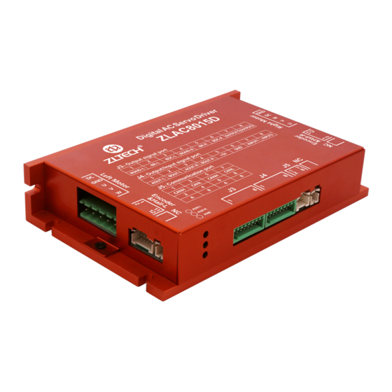
ZLAC8015D
Servo Driver Manual (Special for
Hub Servo Motor)
【 Pl e a s e re a d th e ma n u a l in de t a i l be f o r e us e , to av o i d da m a g e to th e dr i v e r 】
Shenzhen ZhongLing Technology Co.,Ltd.
Add: 8th Floor, Building 3, Qiyu Industrial City, Gongle
Tiezai Rd., Xixiang St., Bao'an Dist, Shenzhen, China
Postcode: 518102
Tel: +86-0755-2979 9302
Fax: +86-0755-2912 4283
Email: sales@zlingkj.com
Web: www.zlingkj.com
Advertisement
Table of Contents

Subscribe to Our Youtube Channel
Related Manuals for ZLTECH ZLAC8015D

Summary of Contents for ZLTECH ZLAC8015D
- Page 1 ZLAC8015D Servo Driver Manual (Special for Hub Servo Motor) 【 Pl e a s e re a d th e ma n u a l in de t a i l be f o r e us e , to av o i d da m a g e to th e dr i v e r 】...
-
Page 2: Table Of Contents
ZLAC8015 Servo Driver Manual (Special for Hub Servo Motor) V2.00 ZLAC8015 Servo Driver Manual (Special for Hub Servo Motor) V2.00 RELEASE NOTES CONTENTS Version Update Time Update Content Updater RELEASE NOTES........................2 PREFACE..........................3 V2.00 2021-02-21 First Edition DHR, LHY SAFETY PRECAUTIONS......................3 1. -
Page 3: Preface
This manual describes the installation, debugging, maintenance, operation and integrated step-servo motor. It should be protected from vibration and shock. other aspects of the servo driver ZLAC8015D. Please read this manual in detail Wiring before use, and be familiar with the safety precautions. -
Page 4: Product Introduction
The alarm can be reset only after the operation signal is cut off. Alarm resetting in the running signal state will cause the integrated step-servo ZLAC8015D is a high-performance digital servo driver for hub servo motor. It has a motor to restart suddenly;... -
Page 5: Electrical, Environmental Index
ZLAC8015 Servo Driver Manual (Special for Hub Servo Motor) V2.00 ZLAC8015 Servo Driver Manual (Special for Hub Servo Motor) V2.00 2. ELECTRICAL, ENVIRONMENTAL INDEX 2.3. INSTALLATION DIMENSION 2.1. ELECTRICIAL INDEX Driver Parameter Min value Typical value Max value Unit Input voltage 20 VDC 36VDC 48VDC... -
Page 6: Driver Interface And Wiring
ZLAC8015 Servo Driver Manual (Special for Hub Servo Motor) V2.00 ZLAC8015 Servo Driver Manual (Special for Hub Servo Motor) V2.00 3. DRIVER INTERFACE AND WIRING 3.1.3 Left/Right motor's incremental encoder and hall port J2/J6 Port Mark Name Function 3.1. INTERFACE DEFINITION 3.1.1 Power wire and power supply input port of left motor Encoder Port... - Page 7 ZLAC8015 Servo Driver Manual (Special for Hub Servo Motor) V2.00 ZLAC8015 Servo Driver Manual (Special for Hub Servo Motor) V2.00 3.1.4 Motor control signal port J3 3.1.6 Communication port J5 Port Mark Function Name Port Mark Name Function CANH CANOPEN Left brake power- BGND-L Left brake control...
-
Page 8: Control Signal Wiring
ZLAC8015 Servo Driver Manual (Special for Hub Servo Motor) V2.00 ZLAC8015 Servo Driver Manual (Special for Hub Servo Motor) V2.00 3.2 CONTROL SIGNAL WIRING ZLAC8015D series driver provides 2 photoelectric isolation programmable input interfaces, compatible with NPN wiring and PNP wiring. Fig.3 Control signal interface wiring diagram 2-channel (IN1-IN2 of J4) programmable input signal is isolated from the external Note: The default input voltage of the control signal is 5V. -
Page 9: Canopen Communication Port Description
Phase current through the motor Over-Current 3 Red ZLAC8015D series driver provides 4PIN communication port. For pin definition, exceeds short-circuit between phases please refer to 3.1.6 Communication Port, which includes CANH, CANL, CANH and CANL. The phase current through the motor...
Need help?
Do you have a question about the ZLAC8015D and is the answer not in the manual?
Questions and answers