
Related Manuals for Logix TC-2000


Summary of Contents for Logix TC-2000
- Page 1 ® Logix TC-2000 Dual Stage Process Controller Operation and Installation Manual Copyright © 2006 Logix ®. All Rights Reserved. Logix is a Registered Trademark of The Controls Group Inc. Kirkland, WA USA...
- Page 2 It is important that the user employ satisfactory overall system design. It is agreed between the buyer and Logix that this is the buyer’s responsibility. It is the responsibility of the installer to ensure that the installation is in compliance with all national and local codes.
-
Page 3: Controller Operation
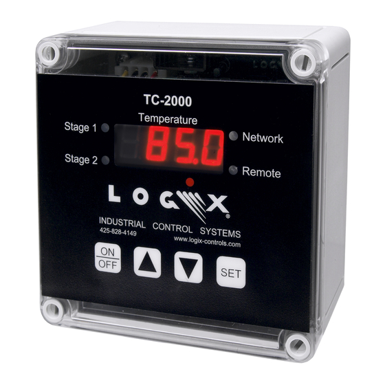
Stage 1 and 2 LEDs - used to indicate the on/off state of each output relay during normal operation. During configuration, the LEDs indicate which stage is being configured. Remote LED - used to indicate the TC-2000 is integrated, monitored and controlled remotely by a Logix® Industrial Control System. -
Page 4: Controller Configuration
Set button. When the controller is activated, the “SP1" prompt will be displayed indicating that it is in the Configuration mode. After leaving the Configuration mode the Set button will remain locked unless the “Loc” parameter was changed to “OFF”. Logix® TC-2000 Process Controller, Page 3 of 7... -
Page 5: Controller Diagnostics
Setting Factory Default Setpoints To change all setpoints back to the factory defaults settings first place the TC-2000 into Standby. Next press and hold Set, Up and Down keys together and then press the On key for 5 seconds. The phrase “dFLT” will appear indicating the default procedure is complete. - Page 6 The relay contact circuit can be combined with or be independent of the controller power circuit. Multiple TC-2000 controllers may share power and relay circuits.
- Page 7 Network Cable Fitting Locations Remove all power sources before opening the TC-2000 enclosure. The network wiring connections are made to the display circuit board mounted in the enclosure cover. Carefully follow the wiring diagrams shown below when connecting the network. The network cable must “daisy-chain”...
-
Page 8: Ordering Information
Warranty and Copyright Information Copyright © 2006 Logix ®. All Rights Reserved. Logix is a Registered Trademark of The Controls Group Inc. Kirkland, WA USA The information contained in this document is subject to change without notice. Logix makes no warranty of any kind with regard to this document, including, but not limited to, the implied warranties of merchantability and fitness for a particular purpose.