
Related Manuals for Meler STARBI

Summary of Contents for Meler STARBI
- Page 1 GLUING SOLUTIONS PATTERN INSTRUCTIONS MANUAL CONTROLLER STARBI BI sw 4.0 svn100 svn100 MA-5151-ENG 151221...
- Page 2 Published by: Focke Meler Gluing Solutions, S. A. P.I. Arazuri-Orkoien, c/B, nº3 A E - 31170 Arazuri - Navarra - Spain Tel.: + 34 948 351 110 e-mail: info@meler.eu www.meler.eu Focke Group Edition December 2021 © Copyright by Focke Meler All rights reserved.
-
Page 3: Table Of Contents
Limited use 2. INTRODUCTION Description Intended use Basic terminology StarBi series range Mods of operation Controller identification Main components Rear connections StarBi 4-6 Outputs Lower connections StarBi 2 Outputs Additional components to the installation Applicators Incremental encoder Pressure regulator Controller bracket... - Page 4 Installation requirements Electrical consumption Unpacking Attaching the device Electrical installation Connection of the peripheral components (StarBi 4-6 Outputs) 1. Output for applicators 2. Input for Photocells 3. Input for encoder 4. Input for 0-10 V signal 5. Output for 0-10 V signal 6.
- Page 5 TABLE OF CONTENTS MA-5151-ENG PATTERN CONTROLLER STARBI 4. USE Start-up and automatic process Change from RUNNING mode to STOPPED mode Change from RUNNING mode to STOPPED mode by inhibit signal Temperature OK Status Error Operating anomalies List of errors and anomalies Screen navigation.
- Page 6 FOCKE MELER GLUING SOLUTIONS TABLE OF CONTENTS 6. TECHNICAL CHARACTERISTICS General Environmental conditions StarBi 2 channels dimensions StarBi 4/6 channels dimensions 7. ACCESSORIES AND SPARE PARTS LIST Spare parts Accessories EC DECLARATION OF CONFORMITY...
-
Page 7: Safety Guidelines
SAFETY GUIDELINES MA-5151-ENG PATTERN CONTROLLER STARBI 1. SAFETY GUIDELINES General The information contained in this section applies not only to everyday equipment operation, but also to any procedure carried out on it, whether for preventive maintenance or in the case of repairs and the replacement of worn out parts. -
Page 8: Electrical Components
FOCKE MELER GLUING SOLUTIONS SAFETY GUIDELINES Electrical components The system works with single-phase of a certain power. Never handle the equipment with the power connected, as this may result in powerful electrical shocks. The installation must be correctly grounded. The installation’s power cable conductors must match the required electric current and voltage. -
Page 9: Intended Use
Note: Do not modify the equipment or use components that were not supplied by Focke Meler. For any modification of a component of the equipment or part of the installation, you must firstly consult the After-Sales Service... - Page 10 FOCKE MELER GLUING SOLUTIONS SAFETY GUIDELINES This page is intentionally left blank.
-
Page 11: Introduction
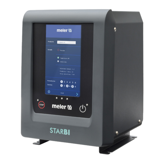
PATTERN CONTROLLER STARBI 2. INTRODUCTION Description Focke Meler’s StarBi pattern controller is a control system for the dispensing and positioning of hot-melt or vinyl glue (cold glue) adhesives in gluing applications. This device has a place in any market related to industrial gluing with hot- melt or cold glue, such as labelling machines, box folding machines, wood lamination, bookbinding…... -
Page 12: Basic Terminology
FOCKE MELER GLUING SOLUTIONS INTRODUCTION Basic terminology Some of the terms used in the instruction manual are described below: Channel: pair of homologous outputs through which the activation signals are transmitted to the applicator. Cycle: period of time that includes the process of applying a product or substrate from the start to the end of it. -
Page 13: Mods Of Operation
INTRODUCTION MA-5151-ENG PATTERN CONTROLLER STARBI Mods of operation The pattern controller has two modes of operation: Manual mode: to enable purging, cleaning or depressurising of the installation or for checking the correct operation of the applicators. The selected outputs are activated by actuating the corresponding button. If the unit was working in automatic mode, it will be stopped when entering the MANUAL MODE screen. -
Page 14: Main Components
4. Button to stop or turn on the program (STOPPED to RUNNING/RUNNING to STOPPED). 5. GREEN LED unit turned on. 6. On/Off button on the screen. 7. Connection for power supply (StarBi 4-6 Outputs). 8. Power input fuse holder. 9. Electrical power supply switch. -
Page 15: Rear Connections Starbi 4-6 Outputs
INTRODUCTION MA-5151-ENG PATTERN CONTROLLER STARBI Rear connections StarBi 4-6 Outputs A. Six inputs for photocells (according to model). E. One input for encoder. B. Six outputs for activation channels of solenoid valves, F. Digital inputs (general inhibition and temperature OK). -
Page 16: Lower Connections Starbi 2 Outputs
FOCKE MELER GLUING SOLUTIONS INTRODUCTION Lower connections StarBi 2 Outputs 2 3 2 4 5 1. Input for photocells (PG13). 4. Analogue inputs/outputs (PG13). 2. Digital inputs/outputs (PG9). 5. Output for activation channels of solenoid valves, two per channel 3. Power input (PG13). -
Page 17: Additional Components To The Installation
PATTERN CONTROLLER STARBI Additional components to the installation Applicators All Focke Meler applicators controlled by 24 VDC solenoid valves (limited by the output power) can be connected. For other devices, consult the Central Office or your nearest Distributor. Detection systems The most suitable detection system (for presence of substrate or start of pattern) will be connected depending on the work to be carried out. -
Page 18: Pressure Regulator
Controller bracket The bracket must be requested separately and there are two types, wall- mounted for 4-6 outputs and articulated wall-mounted for two outputs. Vertical stand StraBi 2 outputs Articulated wall bracket StarBi 2 outputs StarBi wall bracket 4/6 outputs... -
Page 19: Installation
INSTALLATION MA-5151-ENG PATTERN CONTROLLER STARBI 3. INSTALLATION Warning: The pattern controllers are installed in equipment provided with current technologies and with certain foreseeable risks. Therefore, only qualified personnel with sufficient training and experience should be allowed to use, install or repair these devices. -
Page 20: Unpacking
Remove the pattern controller from its packaging and check for any possible damage or breakage. Communicate any damage, including to the external packaging, to your Focke Meler representative or the Focke Meler Main Office. Warning: Reject any packaging that does not have the corresponding labels or whose information does not match what was requested. - Page 21 Make sure that the characteristics of the network match the specifications of the device (see data in this manual and on the nameplate). StarBi 4-6 Outputs: Use the mounting flange of the power connector (supplied with the controller) to avoid false contact problems and the malfunctioning of the unit.
-
Page 22: Connection Of The Peripheral Components (Starbi 4-6 Outputs)
FOCKE MELER GLUING SOLUTIONS INSTALLATION Connection of the peripheral components (StarBi 4-6 Outputs) 1. Output for applicators Double output per channel. Marked for each channel with the numbering 1.1 and 1.2 (channel 1); 2.1 and 2.2 (channel 2), and so on up to 6 channels. -
Page 23: Input For Encoder
INSTALLATION MA-5151-ENG PATTERN CONTROLLER STARBI 3. Input for encoder When using ‘speed reading’ (programming by DISTANCES) it is necessary to have a pulse generator component or analogue input of 0-10 V to know the speed of movement of the substrate. -
Page 24: Input For General Inhibition And Temperature Ok
FOCKE MELER GLUING SOLUTIONS INSTALLATION 6. Input for general inhibition and temperature OK The external input of ‘temperature ok’ (1) prevents the operation of the controller (it remains in STOPPED mode) while the working temperature, in an installation with hot-melt equipment, has not been reached. -
Page 25: Error And Status Warning Output
INSTALLATION MA-5151-ENG PATTERN CONTROLLER STARBI 7. Error and status warning output The ‘error’ signal (1) is activated when an anomaly occurs in the device. It is deactivated when the anomaly disappears or when the alarm is reset, depending on the case. -
Page 26: Additional Configuration
FOCKE MELER GLUING SOLUTIONS INSTALLATION Additional configuration Extra settings Enable / disable temperature ok Shooting autolock Enable inhibition signal The option to ENABLE / DISABLE the temperature OK input has been added. Enable temperature OK signal This permits operation without connecting the melter used to send the signal... -
Page 27: Connection Of The Peripheral Components (Starbi 2 Outputs)
To connect the peripherals in the unit, it is necessary to pass the cable through the corresponding PG cable gland and connect it to the appropriate terminal. Note: Consult Connection of the peripheral components (StarBi 2 Outputs) for more information 1. -
Page 28: Location Of The Peripheral Components
To use another type of photocell or presence of substrate sensor, consult your Focke Meler representative or the Focke Meler Main Office. Encoder The positioning and length of the lines of application and their precision,... -
Page 29: Pressure Regulator
(max. 10 bar), through a built-in filter of 5 µ. The VP-200 has a display that shows the existing pressure at any given moment. To connect other types of devices, consult your Focke Meler Representative or the Focke Meler Main Office. 3-11... - Page 30 FOCKE MELER GLUING SOLUTIONS INSTALLATION This page is intentionally left blank. 3-12...
-
Page 31: Use
MA-5151-ENG PATTERN CONTROLLER STARBI 4. USE This section explains how to use the pattern controller. Although its operation is very user-friendly, it should not be used by untrained personnel. Warning: Improper use may damage the unit itself or injure the person using it. -
Page 32: Change From Running Mode To Stopped Mode
FOCKE MELER GLUING SOLUTIONS Change from RUNNING mode to STOPPED mode 1. With the ‘Automatic shot blocking’ function enabled: Extra settings In STOPPED mode the STOP button’s RED LED stays lit. Press the STOP button to start production. The RED LED shuts off and the unit goes into RUNNING Shooting autolock mode. -
Page 33: Status
MA-5151-ENG PATTERN CONTROLLER STARBI Status When the equipment is in RUNNING mode, the digital output of ‘STATUS’ (closed contact) is activated and the central GREEN LED light turns on. When switching to STOPPED or MANUAL mode, or if the equipment is in READY mode, the GREEN LED turns off and the digital output is deactivated (open contact). -
Page 34: List Of Errors And Anomalies
FOCKE MELER GLUING SOLUTIONS List of errors and anomalies Status of the Type Text of the alarm Description Central LED unit Error Alarm in EV 1 Channel 1 not connected STOPPED Error Alarm in EV 2 Channel 2 not connected... -
Page 35: Interpretation Of The Screens
MA-5151-ENG PATTERN CONTROLLER STARBI STARBI 4.0 Save changes HMI: S02000400 svn100 IO: S02100400 svn100 The ‘SAVE CHANGES’ icon, located in the upper right part of the screen, Extra settings appears in the data entry and programming screens. If the data shown on the Shooting autolock screen is stored, the icon appears with a blue background. -
Page 36: Description Of Screens
FOCKE MELER GLUING SOLUTIONS Description of screens 1. HOME screen. STARBI 4.0 This is the start screen. When it starts, the system displays this screen with the main data of the device. HMI: S02000400 svn100 IO: S02100400 svn100 A- Name of the product selected to work. - Page 37 MA-5151-ENG PATTERN CONTROLLER STARBI STARBI 4.0 2. MENU screen. HMI: S02000400 svn100 IO: S02100400 svn100 Menu Product Installation Manual mode Settings Statistics 3. INSTALLATION screen. TARBI 4.0 STARBI 4.0 To work with products by distances, it is necessary to determine an installation before starting.
- Page 38 FOCKE MELER GLUING SOLUTIONS 4. NEW INSTALLATION screen. TARBI 4.0 STARBI 4.0 After selecting NEW INSTALLATION a screen will open to enter the name; then go to the EDIT INSTALLATION screen. : S02000400 svn100 HMI: S02000400 svn100 : S02100400 svn100...
- Page 39 MA-5151-ENG PATTERN CONTROLLER STARBI 6. EDIT SELECTED INSTALLATION screen. 6 tabs appear, one for each channel (EV). Each tab allows you to edit the STARBI 4.0 distance between the applicator of that channel and each photocell. It also allows you to set the ON and OFF compensation times of that applicator.
- Page 40 FOCKE MELER GLUING SOLUTIONS 8. ENCODER screen. STARBI 4.0 There are 3 options to configure the encoder and only one of them can be active. svn100 HMI: S02000400 svn100 svn100 IO: S02100400 svn100 Installation 2 Installation 2 Saved pulses per meter...
- Page 41 MA-5151-ENG PATTERN CONTROLLER STARBI 9. ANALOGUE INPUT screen. The following screen will appear where you can configure a ramp with 5 dots, ARBI 4.0 STARBI 4.0 defining the conversion between input voltage and line speed. S02000400 svn100 HMI: S02000400 svn100 The maximum input voltage cannot exceed 10 V.
- Page 42 FOCKE MELER GLUING SOLUTIONS 10. COPY INSTALLATION screen. Select the installation to copy. A confirmation message will appear and then a STARBI 4.0 screen will open to enter the name of the new installation. STARBI 4.0 HMI: S02000400 svn100 HMI: S02000400 svn100...
- Page 43 MA-5151-ENG PATTERN CONTROLLER STARBI 12. PRODUCT screen. STARBI 4.0 It is selected from the MENU screen. HMI: S02000400 svn100 IO: S02100400 svn100 Menu Product Edit product Product Installation New product Copy product Delete product Manual mode Settings Statistics 13. SELECT PRODUCT screen.
- Page 44 FOCKE MELER GLUING SOLUTIONS 14. NEW PRODUCT screen. STARBI 4.0 It is selected from the PRODUCT screen. Once the type of product is selected, an editing screen is opened depending on the type of product chosen. HMI: S02000400 svn100 IO: S02100400 svn100...
- Page 45 MA-5151-ENG PATTERN CONTROLLER STARBI 16. COPY PRODUCT screen. It is selected from the PRODUCT screen. A confirmation message will appear STARBI 4.0 and then a screen will open to enter the name of the new product. STARBI 4.0 HMI: S02000400 svn100...
- Page 46 RBI 4.0 FOCKE MELER GLUING SOLUTIONS 2000400 svn100 2100400 svn100 New product 18. EDITING PRODUCT BY TIME screen. The screen appears when you name a new product from the NEW PRODUCT STARBI 4.0 screen or if you select an existing one from the EDIT PRODUCT screen. The...
- Page 47 STARBI 4.0 HMI: S02000400 svn100 MA-5151-ENG PATTERN CONTROLLER STARBI IO: S02100400 svn100 New product 20. ADVANCED PARAMETERS screen. Other parameters can be configured in addition to the patterns. The keyboard STARBI 4.0 Time product Distance product opens when pressing on the text boxes. After entering the value it will be HMI: S02000400 svn100 visible in the text box.
- Page 48 New product FOCKE MELER GLUING SOLUTIONS Time product Distance product 22. ADVANCED PARAMETERS screen. Variable Variable Other parameters can be configured in addition to the patterns. The keyboard time product distance product opens when pressing on the text boxes. After entering the value it will be visible in the text box.
- Page 49 Time product Distance product MA-5151-ENG PATTERN CONTROLLER STARBI Variable Variable time product distance product 24. ADVANCED PARAMETERS screen. Other parameters can be configured in addition to the patterns. The keyboard STARBI 4.0 Repetitive Repetitive opens when pressing on the text boxes. After entering the value it will be...
- Page 50 FOCKE MELER GLUING SOLUTIONS New product 26. ADVANCED PARAMETERS screen. STARBI 4.0 These parameters are configured in the same way as the products by times Time product Distance product but with values in millimetres (mm). The analogue outputs are configured in HMI: S02000400 svn100 ramp mode to have a variable output depending on the speed.
- Page 51 IO: S02100400 svn100 New product MA-5151-ENG PATTERN CONTROLLER STARBI Time product Distance product 28. ADVANCED PARAMETERS screen. These parameters are configured in the same way as the products by times but with STARBI 4.0 STARBI 4.0 Variable Variable values in millimetres (mm). The analogue outputs are configured in ramp mode to...
- Page 52 Time product Distance product FOCKE MELER GLUING SOLUTIONS Variable Variable time product distance product 30. ADVANCED OPTIONS screen. These parameters are configured in the same way as the products by times STARBI 4.0 Repetitive Repetitive time product distance product but with values in millimetres (mm). The analogue outputs are configured in ramp mode to have a variable output depending on the speed.
- Page 53 MA-5151-ENG PATTERN CONTROLLER STARBI 32. MANUAL MODE screen. Here each of the outputs can be activated and deactivated manually. This STARBI 4.0 mode enables purging, cleaning or depressurising the installation, or checking the correct operation of the applicators. HMI: S02000400 svn100...
- Page 54 FOCKE MELER GLUING SOLUTIONS 34. Selection of CONFIGURATION screen. TARBI 4.0 STARBI 4.0 It is selected from the MENU screen. S02000400 svn100 HMI: S02000400 svn100 S02100400 svn100 IO: S02100400 svn100 Menu Configuration Password Extra settings Product Installation Restore default Manual mode...
- Page 55 MA-5151-ENG PATTERN CONTROLLER STARBI 36. DATE AND TIME screen. From the HOME screen, the ‘Date and Time’ menu can be accessed directly. TARBI 4.0 STARBI 4.0 The following screen will appear where you can see and modify the date and time of the system.
-
Page 56: Password Management
Whenever there is activity on the screen, the system remains in this mode. If the end of this 15 minutes is reached, the unit returns to USER mode. If you forget the EXPERT level password, contact the Focke Meler main offices to find out how to proceed to recover it. - Page 57 MA-5151-ENG PATTERN CONTROLLER STARBI • Automatic shot blocking. Enables or disables the automatic shot blocking function. Note: For more information see the point ‘Automatic shot blocking’. • Enable inhibit signal: Enables or disables the external inhibit signal from a main machine or a PLC, so that it is possible to pass with this signal from STOPPED mode (0 V) to RUNNING mode (24 V) and vice versa.
- Page 58 FOCKE MELER GLUING SOLUTIONS 40. Selection of STATISTICS screen. It is selected from the MENU screen. it shows the total amount of products TARBI 4.0 STARBI 4.0 produced and the total and partial amount of a specific product produced. It also allows you to reset these values.
-
Page 59: Automatic Shot Blocking' Enabled
MA-5151-ENG PATTERN CONTROLLER STARBI ‘Automatic shot blocking’ function The unit has a function that activates automatic shot blocking after a voltage loss, a direct disconnection from the network, or when the unit exits RUNNING status. This function can be enabled or disabled from the ‘Additional settings’ screen. -
Page 60: Application For Pc
• Update the IOC board software. • Make a complete backup of the system. • Restore a complete backup of the system. (*) http://www.meler.eu Warning: For more information consult your Focke Meler Representative or the Focke Meler Main Office. 4-30... -
Page 61: Mantenance
Do not replace the cable with another one of a type that is different from that provided by the equipment or recommended by Focke Meler. If in doubt, please check with your Focke Meler Representative or the Focke Meler Main Office. -
Page 62: Calibrate The Screen
FOCKE MELER GLUING SOLUTIONS MANTENANCE Calibrate the screen If necessary, it is possible to calibrate the touchscreen. Disconnect the power supply from the equipment. Open the front door to access the HMI card. Lower microswitch 8 on the HMI card to the OFF position. - Page 63 Supply voltage 100-240V ±10% Frequency 50/60Hz Protection fuse StarBi 2 outputs: 2A FF 6.3x32 • StarBi 4/6 outputs: 3.15A FF 6.3x32 StarBi 6 Outputs ---- 154W Total Power StarBi 4 Outputs ---- 104W StarBi 2 Outputs ---- 54W Channel Power...
- Page 64 FOCKE MELER GLUING SOLUTIONS TECHNICAL CHARACTERISTICS Environmental conditions Interior use Altitude up to 2,000m. Room temperature between 5ºC and 40ºC Relative maximum humidity of 80% for temperatures up to 31ºC, decreasing linearly to 50% relative humidity to 40ºC Voltage fluctuations of the supply NETWORK which do not surpass ±10%...
- Page 65 PROGRAMADOR DISPAROS STARBI-2-PNP-I0-0B HOJA Nº/ SUS. A/ REPLAC SHEET NUMBER 1 de 1 CATEGO RATE Este plano es propiedad exclusiva de MELER GLUING SOLUTIONS Todos los derechos reservados. This drawing is owned sole of MELER GLUING SOLUTIONS All rights reserved.
- Page 66 REFERENCIA/ RE SHEET NUMBER 1 de 1 2203 Este plano es propiedad exclusiva de MELER APLICADORES DE HOT - MELT S.A. Todos los derechos reservados. This drawing is owned sole of MELER APLICADORES DE HOT- MELT S.A. All rights reserved.
- Page 67 ACCESSORIES AND SPARE PARTS LIST MA-5151-ENG PATTERN CONTROLLER STARBI 7. ACCESSORIES AND SPARE PARTS LIST The list of the most common spare parts in the time controller device appears in this chapter in order to provide a quick and reliable guide to choosing them.
- Page 68 FOCKE MELER GLUING SOLUTIONS ACCESSORIES AND SPARE PARTS LIST Spare parts Nº Ref. Description 150030490 Fuse 3.15 A 6.3x32 (for units with 4 or 6 outputs) 150025640 Fuse 2 A 6.3x32 (for units with 2 outputs) 150030600 Power supply 24 VDC 8.4 A (6 outputs) 150030610 Power supply 24 VDC 6.5 A (4 outputs)
- Page 69 150060140 Solenoid valve cable 5/2 UF 10 m connection to terminals 150030400 * Solenoid valve cable 5/2 UF 3 m M12 connection (Starbi 4/6 outputs) 150030820 * Solenoid valve cable 5/2 UF 6 m M12 connection (Starbi 4/6 outputs) 150031050 * Solenoid valve cable 5/2 UF 9 m M12 connection (Starbi 4/6 outputs) (*) Only for Solenoid valve cable 5/2 24DVC 12W UF ref.
- Page 70 VP-200 pressure regulator accessory kit 150030480 VP-200 pressure regulator accessory kit M12 connection (Starbi 4/6 outputs) 150031250 Aerial connector VP-200 Starbi connection M12 with 3m of cable (Starbi 4/6 outputs) 115002450 Extension 3m. applicator series 33A Starbi M12 (Starbi 4/6 outputs) 150123770...
- Page 71 EC DECLARATION OF CONFORMITY Original Declaration Product: PATTERN CONTROLLER The manufacturer: Focke Meler Gluing Solutions, S.A. Pol. Arazuri-Orkoien, c/B, nº3 A E-31170 Arazuri - Navarra - Spain — Focke Group — This declaration of conformity is issued under the sole responsibility of the manufacturer.
- Page 72 For more information speak with your Focke Meler representative: Focke Meler Gluing Solutions, S. A. P.I. Arazuri-Orkoien, c/B, nº3 A E - 31170 Arazuri - Navarra - Spain Phone: +34 948 351 110 info@meler.eu - www.meler.eu Focke Group...
Need help?
Do you have a question about the STARBI and is the answer not in the manual?
Questions and answers