Endress+Hauser Deltabar FMD72 Brief Operating Instructions
Electronic differential pressure for level measurement
Hide thumbs
Also See for Deltabar FMD72:
- Operating instructions manual (108 pages) ,
- Technical information (64 pages) ,
- Manual (72 pages)
Table of Contents
Advertisement
Quick Links
Brief Operating Instructions
Deltabar FMD72
Electronic differential pressure for level measurement
These Instructions are Brief Operating Instructions; they do not replace the
Operating Instructions included in the scope of supply.
For detailed information, refer to the Operating Instructions and other
documentation on the CD-ROM provided or visit "www.endress.com/
deviceviewer".
KA01105P/00/EN/02.12
71191242
Advertisement
Table of Contents

Related Manuals for Endress+Hauser Deltabar FMD72


Summary of Contents for Endress+Hauser Deltabar FMD72
- Page 1 Brief Operating Instructions Deltabar FMD72 Electronic differential pressure for level measurement These Instructions are Brief Operating Instructions; they do not replace the Operating Instructions included in the scope of supply. For detailed information, refer to the Operating Instructions and other documentation on the CD-ROM provided or visit "www.endress.com/...
-
Page 2: Table Of Contents
9.4 Operating the device using onsite display (optional) ......24 9.5 Operation using Endress+Hauser operating program ......27 9.6 Operation using Field Xpert SFX100 . -
Page 3: Document Information
Further standard device documentation The document types listed are available: • On the CD supplied with the device • In the Download Area of the Endress+Hauser Internet site: www.endress.com ® Download Technical Information TI01033P: helps in planning your device The document contains all the technical data on the device and provides an overview of the accessories and other products that can be ordered for the device. -
Page 4: Document Conventions
Document information Deltabar FMD72 1.1.3 Safety Instructions (XA) Safety Instructions (XA) are supplied with the device depending on the approval. These instructions are an integral part of the Operating Instructions. Certificate/type of protection Documentation Version in the order code ATEX II 1/2G Ex ia IIC T6 Ga/Gb... - Page 5 Deltabar FMD72 Document information 1.2.2 Electrical symbols Symbol Meaning Direct current A terminal to which DC voltage is applied or through which direct current flows. A0011197 Alternating current A terminal to which alternating voltage is applied or through which alternating current flows.
-
Page 6: Basic Safety Instructions
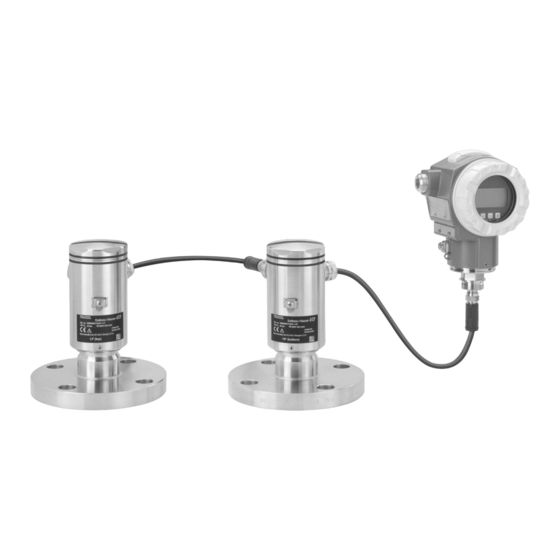
Must comply with all instructions and the regulatory framework. ► Designated use 2.2.1 Application and media The Deltabar FMD72 is a differential pressure transmitter for measuring differential pressure and level in pressurized tanks. The device has two sensor modules, which measure the operating Endress+Hauser... -
Page 7: Workplace Safety
The manufacturer is not liable for damage caused by improper or non-designated use. Verification for borderline cases: For special fluids and fluids for cleaning, Endress+Hauser is glad to provide assistance in ► verifying the corrosion resistance of fluid-wetted materials, but does not accept any warranty or liability. -
Page 8: Product Safety
It fulfills general safety requirements and legal requirements. It also conforms to the EC directives listed in the device-specific EC declaration of conformity. Endress+Hauser confirms this fact by applying the CE mark. Product description See the Operating Instructions BA01044P on the CD-ROM provided. - Page 9 Deltabar FMD72 Incoming acceptance and product identification A0016052 A0015502 A0016053 Are the goods undamaged? DELIVERY NOTE Made in Germany, D-79689 Maulburg A0015502 Order code: Ser. no.: Ext. order code: Span ex works SW: Dev.Rev.: A0016054 Do the data on the nameplate correspond to the order specifications and the...
-
Page 10: Product Identification
Are the CD-ROM (product documentation) and documentation present? If required (see nameplate): Are the safety instructions (XA) present? If one of these conditions is not met, please contact your Endress+Hauser sales office. Product identification The following options are available for identification of the measuring device: •... -
Page 11: Storage And Transport
Deltabar FMD72 Storage and transport Storage and transport Storage conditions Use original packaging. 5.1.1 Storage temperature range –40 to +80 °C (–40 to +176 °F) Transporting the product to the measuring point WARNING Risk of damage to housing! Risk of injury. -
Page 12: Installation
Installation Deltabar FMD72 Installation When measuring in media containing solids, such as dirty liquids, installing separators and drain valves is useful for capturing and removing sediment. Mounting dimensions For dimensions, see the "Mechanical construction" section in TI01033P. Mounting location The FMD72 is best suited to level measurement in tanks with pressure overlay, high distillation columns and other containers with changing ambient temperatures. -
Page 13: Installing The Sensor Modules
Deltabar FMD72 Installation max. 380° 2 mm A0017506 Installing the sensor modules • The nameplate on the sensor module specifies where the sensor module is typically installed: HP (bottom) LP (top) For further information see the "Function" section. • Due to the orientation of the sensor modules, there may be a shift in the zero point, i.e. when the container is empty or partially full, the measured value does not display zero. -
Page 14: Seal For Flange Mounting
Installation Deltabar FMD72 A0017512 Seal for flange mounting NOTICE Distorted measurement results. The seal is not allowed to press against the process isolating diaphragm as this could affect the measurement result. Ensure that the seal is not touching the process isolating diaphragm. -
Page 15: Electrical Connection
Deltabar FMD72 Electrical connection Is the device adequately protected from precipitation and direct sunlight? Are the securing screw and securing clamp tightened securely? Electrical connection WARNING If the operating voltage is > 35 VDC: Dangerous contact voltage at terminals. Risk of electric shock! In a wet environment, do not open the cover if voltage is present. -
Page 16: Connecting The Sensor Module Hp To The Transmitter
Electrical connection Deltabar FMD72 2 3 4 NPT ½" A0017528 BK (black) BU (blue) WH (white) BN (brown) Sensor module LP Sensor module HP Ground terminal Torque 0.4 Nm 7.1.1 Screening with cable shield Screening with cable shield is described in the associated documentation SD00354P. The documentation is provided with the connecting cables. - Page 17 Deltabar FMD72 Electrical connection • Screw on the housing cover of the terminal compartment of the sensor module HP. • Guide the cable of the transmitter through the cable gland of the sensor module HP. Use the shielded 4-wire cable that is provided. The wire ends are color-coded to match the corresponding terminal.
-
Page 18: Connecting The Measuring Unit
Electrical connection Deltabar FMD72 Connecting the measuring unit 7.3.1 Wiring the transmitter WARNING Supply voltage switched off? Risk of electric shock and/or explosion! Switch off the supply voltage before connecting the device. ► • When using the measuring device in hazardous areas, installation must comply with the corresponding national standards and regulations and the Safety Instructions or Installation or Control Drawings. - Page 19 Deltabar FMD72 Electrical connection 4…20 mA Test Test Test 4... 20mA 4... 20mA Test A0017530 Housing 4 to 20 mA test signal between positive and test terminal External ground terminal Internal ground terminal Jumper for 4 to 20 mA test signal Minimum supply voltage = 12 V DC, jumper is set as illustrated in the diagram.
-
Page 20: Connection Conditions
Electrical connection Deltabar FMD72 Connection conditions 7.4.1 Cable specification for transmitter connection See Operating Instructions BA01044P on the CD-ROM supplied. 7.4.2 Cable glands See Operating Instructions BA01044P on the CD-ROM supplied. 7.4.3 Overvoltage protection (optional) See Operating Instructions BA01044P on the CD-ROM supplied. -
Page 21: Operation Without An Operating Menu
Deltabar FMD72 Operation without an operating menu Operation without an operating menu Position of operating elements 8.1.1 Operating keys on the exterior of the device With the T14 housing (aluminum or stainless steel), the operating keys are located either outside of the housing, under the protection cap or inside on the electronic insert. - Page 22 Operation without an operating menu Deltabar FMD72 8.1.2 Operating keys and elements located internally on the electronic insert 1 2 3 Display HART FIELD COMMUNICATION PROTOCOL Sensor A0016500 DIP switch for locking/unlocking parameters relevant to the measured value DIP switch for switching damping on/off DIP switch for alarm current SW/Alarm min (3.6 mA)
-
Page 23: Operation With An Operating Menu
Deltabar FMD72 Operation with an operating menu 8.1.4 Function of the operating elements Operating Meaning key(s) Press Adopt lower range value. A reference pressure is present at least 3 seconds the device. For a detailed description, see also "Pressure measuring A0017535 mode"... -
Page 24: Operating Options
Operation with an operating menu Deltabar FMD72 Operating options 9.3.1 Local operation A0017650 Display and operating module with push buttons. Cover must be opened for operation. 9.3.2 Remote operation via HART See Operating Instructions BA01044P on the CD-ROM supplied. Operating the device using onsite display (optional) A 4-line liquid crystal display (LCD) is used for display and operation. - Page 25 Deltabar FMD72 Operation with an operating menu 9.4.2 Overview – A0016498 Operating keys Bargraph Symbol Header Parameter ID number 9.4.3 Symbols on the onsite display Error symbols See Operating Instructions BA01044P on the CD-ROM supplied. Display symbols for locking status See Operating Instructions BA01044P on the CD-ROM supplied.
- Page 26 Operation with an operating menu Deltabar FMD72 Operating key(s) Meaning • Confirm entry • Jump to the next item • Selection of a menu item and activation of edit mode A0017881 Contrast setting of onsite display: darker A0017879 A0017881 Contrast setting of onsite display: brighter...
-
Page 27: Operation Using Endress+Hauser Operating Program
Exit edit mode for the parameter with F. Confirm User-definable parameters See Operating Instructions BA01044P on the CD-ROM supplied. Operation using Endress+Hauser operating program See the Operating Instructions BA01044P on the CD-ROM provided. Operation using Field Xpert SFX100 See the Operating Instructions BA01044P on the CD-ROM provided. -
Page 28: Function Check
Commissioning Deltabar FMD72 10.1 Function check Before commissioning your measuring point, ensure that the post-installation and post- connection check have been performed. • "Post-mounting check" checklist • "Post-connection check" checklist 10.2 Unlocking/locking configuration If the device is locked to prevent configuration, it must first be unlocked. - Page 29 Deltabar FMD72 Commissioning • The pressure applied must be within the nominal pressure limits of the respective sensor module. See information on the nameplate. • Operation must be unlocked, see "Unlocking/locking configuration" section (® ä 28). • The S and O keys have a function only in the case of the "Calibration Mode Wet" setting.
-
Page 30: Commissioning With An Operating Menu
Commissioning Deltabar FMD72 Set the upper pressure value. Desired pressure for upper pressure value ("Full Pressure" ) is present at device. O Press key for at least 3 s. Does the LED on the electronic insert light up briefly? Applied pressure was saved as the upper pressure value ("Full Applied pressure was not saved as the upper Pressure") and assigned to the upper level value ("Full... - Page 31 Deltabar FMD72 Commissioning 10.5.2 Configuring language via operating tool (FieldCare) See the Operating Instructions BA01044P on the CD-ROM provided. 10.5.3 Measuring mode selection Measuring mode (005) Navigation Setup ® Measuring mode Write permission Operators/Service engineers/Expert Description Select the measuring mode.
-
Page 32: Pos. Zero Adjust
Commissioning Deltabar FMD72 10.5.5 Press. Eng. Unit selection Press. Eng. Unit (125) Navigation Setup ® Press. Eng. Unit Write permission Operators/Service engineers/Expert Description Select the pressure engineering unit. If a new pressure engineering unit is selected, all pressure-specific parameters are converted and displayed with the new unit. -
Page 33: Configuring Level Measurement
Deltabar FMD72 Commissioning Navigation Setup ® Pos. Zero Adjust Write permission Operators/Service engineers/Expert Description Position adjustment – the pressure difference between zero (set point) and the measured differential pressure need not be known. Options • Confirm • Cancel Example • Measured value = 2.2 mbar (0.033 psi) •... - Page 34 Commissioning Deltabar FMD72 10.7.2 Overview of level measurement Measuring task Level Measured variable Description Measured value Selection options display Calibration is "In pressure" Via the "Unit before lin. • Calibration with The measured value performed by entering (025)" parameter : %, reference pressure (wet display and the "Level...
- Page 35 Deltabar FMD72 Commissioning • The values entered for "Empty Calib./Full Calib.", "Empty Pressure/Empty Pressure" and "Set LRV/Set URV" must be at least 1% apart. The value will be rejected, and a warning message displayed, if the values are too close together. Further limit values are not checked, i.e.
- Page 36 Commissioning Deltabar FMD72 Description Select the "Dry" option via the "Calibration mode (027)" parameter. Menu path: Setup ® Extended Setup ® Level ® Calibration Mode 1000 Enter the volume value for the lower calibration point via the "Empty Calib. (028)" parameter, here 0 liters for example.
-
Page 37: Linearization
Deltabar FMD72 Commissioning Description If the process uses a medium other than that on which the calibration was based, the new density must be specified in the "Process Density" parameter. Menu path: Setup ® Extended Setup ® Current Output ® Process Density. - Page 40 *71191242* KA01105P/00/EN/02.12 71191242 71191242 CCS/COSIMA...
Need help?
Do you have a question about the Deltabar FMD72 and is the answer not in the manual?
Questions and answers