Advertisement
Quick Links
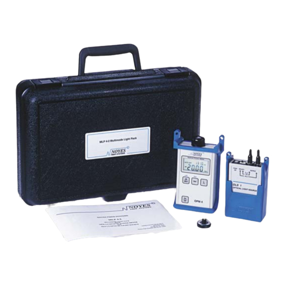
MLP 4-2 Fiber Optic Loss Test Kit
Description
The MLP 4-2 Test Kit offers accurate fi ber optic testing at an
affordable price. Combining the OPM 4-2C Optical Power
Meter and the OLS 1-2 Optical Light Source in a rugged
carry case, the MLP 4-2 is a complete Test Kit for fi ber
optic LAN's, and WAN's.
Multimode Fiber Link Insertion Loss Testing
Transmit Jumper
Transmit
(same core size, 50
Jumper
or 62.5µm, as link)
5 wraps
Mandrel
1
1 Attach Mandrel to Transmit Jumper
Wrap the transmit jumper fi ve times around the mandrel and attach
it to the output port of the OLS 1 (LED source).
Note: The transmit and receive jumpers must use same fi ber type
(50 or 62.5µm) as link.
2 Set Reference (One Jumper Method)
Connect the output of the OLS 1 directly to the input of the OPM 4
(optical power meter). Then press and hold the Ref (set reference)
key until the word "HELD" appears. When you release the Ref
key, the OPM 4 should display "0 dB" (+/- 0.05 dB) indicating
that the power measured at output of the transmit jumper has
been recorded as the reference level for your insertion loss
measurements.
Transmit
Jumper
Mandrel
Wrap
0 dB
OLS 1
OPM 4
2
www.noyes-fi ber.com
Loss Measurements at 850 and 1300 nm
Multimode and Singlemode Testing
Set Reference for Each Wavelength
Small Size, Field Portable, Battery Operated
Auto or Manual Power Off
N.I.S.T. Traceable
Used during installations or maintenance, the MLP 4-2
performs insertion loss measurements on multimode fi ber
at 850 and 1300nm, as well as singlemode fi ber at 1300nm.
The auto zero feature stores reference values at each
wavelength for direct loss readings in dB.
Adapter
Receive
Transmit
Jumper
Jumper
Mandrel
Wrap
0.4 dB
OLS 1
OPM 4
3
3 Check Jumpers
Disconnect the transmit jumper from the OPM 4 (be sure NOT to
remove the end of the jumper connected to the OLS 1). Attach the
receive jumper to the OPM 4. Mate the free ends of the transmit
and receive jumpers. Verify that the insertion loss of this mated
connector pair is well under 0.75 dB, the maximum allowed by
the TIA. Noyes recommends that the loss of your mated test
jumpers be < 0.4 dB. If not, clean both jumpers and repeat
steps 2 and 3.
4 Test Links
Connect the OLS 1 and OPM 4 to opposite ends of each link to be
tested. Take insertion loss measurements.
NOYES
AFL Telecommunications
Link under test
OLS 1
OPM 4
4
Receive
Jumper
3.2 dB
Advertisement

Related Manuals for Noyes MLP 4-2


Summary of Contents for Noyes MLP 4-2
- Page 1 Auto or Manual Power Off N.I.S.T. Traceable Description The MLP 4-2 Test Kit offers accurate fi ber optic testing at an Used during installations or maintenance, the MLP 4-2 affordable price. Combining the OPM 4-2C Optical Power performs insertion loss measurements on multimode fi ber Meter and the OLS 1-2 Optical Light Source in a rugged at 850 and 1300nm, as well as singlemode fi...
- Page 2 -30 to 60°C Specifi cations are subject to change. Ordering Information AFL Telecommunications The MLP 4-2 test kit includes an OPM 4-2C, OLS 1-2, ST Noyes Fiber Systems adapter cap, carry case, protective rubber boots, 50 and 62.5µm 16 Eastgate Park Road mandrels for 3µm test jumpers, carry case, and operations...
Need help?
Do you have a question about the MLP 4-2 and is the answer not in the manual?
Questions and answers