
Related Manuals for Noyes TURBOTEST 400


Summary of Contents for Noyes TURBOTEST 400
- Page 1 Noyes TurboTest 400 Specs Provided by www.AAATesters.com TURBOTEST 400 Fiber Optic Certification Test Set User’s Guide T e s t & I n s p e c t i o n...
- Page 2 TURBOTEST 400 Fiber Optic Certification Test Set User’s Guide T e s t & I n s p e c t i o n © 2002, AFL Telecommunications, all rights reserved. T400-00-1000 Revision D, 9.09.05 Specifications are subject to change without notice.
- Page 3 Any product found to be defective within the warranty period would be repaired or replaced by Noyes. In no case will Noyes liabilities exceed the original purchase price of the product.
-
Page 4: Table Of Contents
Table of Contents Table of Contents Safety Information Important Safety Information ................iv Section 1: General Information Contacting Noyes Customer Service ..............1 Unpacking and Inspection .................1 Feature Overview....................2 Recommended Accessories................2 Section 2: Functional Description Main Unit ......................3 Remote Unit .....................4 Section 3: Setup and Operation Setting an AutoTest Reference ................5... - Page 5 Installing New Main and Remote Unit Software ...........19 to install new software...................19 Section 7: Specifications TURBOTEST 400 Specifications ................21 Model T410 Multimode AutoTest Rules...............22 multimode commercial building (premises) cabling standards ......22 multimode application standards ..............22 Model T420 Singlemode AutoTest Rules.............23...
- Page 6 Figure 4-2. AutoTest Setup (2nd part of a two-way test)........13 Figure 4-3. AutoTest Setup................14 Section 5: Maintenance Figure 5-1. Cleaning Optical Ports..............15 Figure 5-2. Removing Battery Compartment Cover..........16...
-
Page 7: Safety Information
NOTICE! The T400 contains no user serviceable parts. Except for changing batteries and cleaning optical ports, this instrument must be returned to Noyes or authorized agents for repair and calibration. CAUTION! Proper care in handling should be taken when using any precision optical test equipment such as the T400. -
Page 8: Section 1: General Information
T400 units and recommended accessories, or if you need technical or sales support, please contact Noyes Customer Service. Contacting Noyes Customer Service You may call Noyes Customer Service between 8 a.m. and 5 p.m., United States Eastern Time, as follows: Tel:... -
Page 9: Feature Overview
T400 User’s Guide Feature Overview The TURBOTEST 400 models T410 (multimode) and T420 (singlemode) are designed to quickly test (AutoTest) loss and length of fiber links, then provide PASS/FAIL results based on your selected standards. Using the supplied WinTest 400 Software, certification reports can be created based on the latest fiber standards or user defined rules. -
Page 10: Section 2: Functional Description
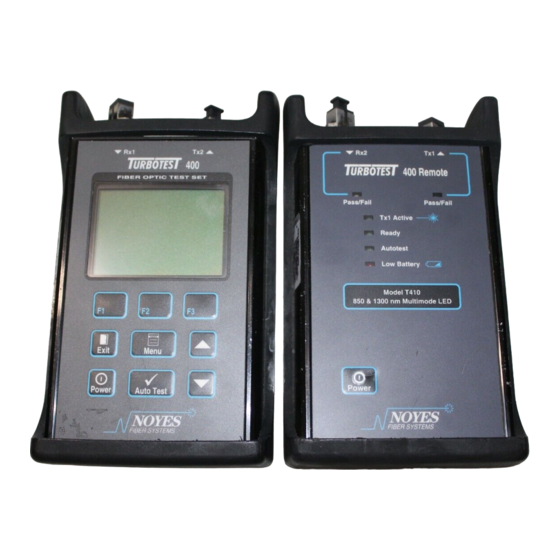
Modular Adapter Cap to a PC and software updates Optical Transmit Port (Tx2) - modular adapter Optical Receive Port ( Rx1) - accepts NOYES thread-on modular adapter caps. FIBER OPTIC TEST SET REFERENCE IS Display - used to show various... -
Page 11: Remote Unit
Modular Adapter Cap to a PC and software updates Optical Transmit Port (Tx1) - Optical Receive Port ( Rx2) - modular adapter accepts NOYES thread-on modular adapter caps Test Pass/Fail Indicators - based on selected test rule. 400 Remote Pass /Fail... -
Page 12: Section 3: Setup And Operation
Section 3 Section 3: Setup and Operation This chapter describes how to set the Main and Remote Units for operation, and to program user preferences. The SETUP (F1) and REF (F3) keys on the AutoTest screen provide the most used setup options for conducting AutoTests. -
Page 13: Saving Test Results
T400 User’s Guide 2 From the AUTOTEST screen press REF (F3). The Main Unit will display the current reference levels at both wavelengths. 3 Press SET REF (F3). 4 The new reference levels will be displayed. • If the new reference levels are acceptable (T410: -20 ±1 dBm , T420: -10 ±1 dBm), then press SAVE (F3). -
Page 14: To Specify Starting Fiber Numbers
Section 3 2 Highlight the Side 1 fiber name (e.g. FIBER), then press CHANGE (F3). Side 2 Side 1 3 Use the arrow keys (F1 & F2) and the SELECT (F3) key to enter characters. Use the MAIN MENU key as a backspace. Press EXIT when finished. OPTIONAL: To make Side 2 fiber name different from Side 1 name highlight the Side 2 fiber name. -
Page 15: To Review Test Results
T400 User’s Guide OPTIONAL: To independently change the Side 2 fiber number, highlight it and use the F1 or F2 keys to change. 3 Highlight either number, press CHANGE (F3), then use the F1, F2 and ARROW keys to create the desired starting numbers for Side 1 and Side 2. -
Page 16: Selecting Autotest Rules
Section 3 Selecting AutoTest Rules The Main Unit can compare test results with AutoTest rules based on industry standards, or up to four user-defined rules. To pass, all parts of the chosen rule must be met. For a complete list of AutoTest rules refer to Section 7. -
Page 17: Connecting To A Pc
T400 User’s Guide General Setup Options To change the following Main Unit options perform the following steps. 1 From the MAIN MENU select OPTIONS. Screen 1 will appear listing the following options. Use the ARROW keys to highlight the parameter to be changed, then use the - (F1) or + (F2) key to adjust the selected parameter. -
Page 18: Power Meter Referencing
Section 3 Using the Main Unit as a Power Meter To use the Main Unit as an optical power meter and light source, or to use the Main Unit as an optical power meter with a separate light source, perform the following steps. power meter referencing 1 Clean and connect the test jumper to the Main Units receive port (Rx1) and the Light Source’s output port. - Page 19 NOTE: When the battery life reaches about 5%, the Low Battery LED on the Remote Unit will turn on. Refer to Section 5 for battery replacement procedures. 3 Again, press the DOWN ARROW key. Screen 3 of 3 will appear listing contact information for Noyes.
-
Page 20: Section 4: Autotest Procedures
Section 4 Section 4: AutoTest Procedures This section describes how to perform AutoTests using the Main and Remote Units or the Main Unit with a far end loop-back test jumper. NOTE: The loop-back procedure calculates the average loss of two fibers and thus is not recommended for fiber certification. -
Page 21: Conducting A Loop-Back Autotest
T400 User’s Guide Conducting a Loop-Back AutoTest NOTE: The loop-back procedure calculates the average loss of two fibers and thus is not recommended for fiber certification. 1 Set a Loop-Back AutoTest Reference. If this has already been done, skip to step 2. 2 Select an AutoTest rule. -
Page 22: Section 5: Maintenance
Section 5: Maintenance Repair and Calibration Repair of these units in the field is NOT recommended. If repair is necessary, please contact Noyes. Calibration of the Main and Remote Units are recommended every 12 months. Please contact Noyes for proper calibration. -
Page 23: Cleaning Receive Ports (Rx1 & Rx2)
T400 User’s Guide 7 Replace the dust cap. cleaning receive ports (Rx1 & Rx2) 1 Remove the dust cap on the adapter cap (Refer to Figure 5-1). 2 Unscrew the adapter cap from the adapter cap mount. 3 Dampen an optical wipe with the alcohol and gently wipe the optical port on the adapter mount. Then dry the optical port using a new optical wipe. -
Page 24: Section 6: Wintest 400 Software
WinTest 400 is a Windows based application that provides the ability to transfer stored AutoTest results files from a TURBOTEST 400 Main Unit. Once the files have been transferred, certification reports can be generated for the tested optical fibers listing AutoTest results, along with company, operator, and job information. -
Page 25: Getting Started
T400 User’s Guide Getting Started This section provides you with a quick overview of WinTest 400 operation. As shown below, WinTest 400 displays test results transferred from the Main Unit and provides fields for entering company, user, and job information. NOTE: If you wish to have the same header information (company and user information) appear in all the files transferred from the Main Unit, then before transferring close the current file (if one is open), enter the required information into the appropriate fields. -
Page 26: To Open, Print And Save Files
files 1 To open TURBOTEST 400 AutoTest files, select File, locate the file that you wish to view, then click Open. Test results will appear in the lower part of the screen. Header information (if previously entered) will appear in the top part of the screen. - Page 27 6 From the Open menu browse and select the file containing the new Main (or Remote) Unit software, then click OPEN. WinTest 400 will establish connection with the Main (or Remote) Unit and begin software installation. NOTE: Do not disconnect the serial cable or depower your TURBOTEST 400 units or PC until software installation is done.
-
Page 28: Section 7: Specifications
Section 7 Section 7: Specifications TURBOTEST 400 Specifications Transmit Port Specifications Model T410 T420 Emitter type Laser Class I (FDA 21 CFR 1040.10 & Emitter classification Class I 1040.11; EN 60825-1:1994) AutoTest wavelengths 850 / 1300 nm 1310 / 1550 nm Power (average) -20 dBm (62.5 µm) -
Page 29: Model T410 Multimode Autotest Rules
T400 User’s Guide Model T410 Multimode AutoTest Rules Multimode Commercial Building (Premises) Cabling Standards Rule T410 Name Total Loss Total Loss Length Fiber Loss Fiber Loss Loss per Loss per @ 850 nm @ 1300 nm @ 850 nm @ 1300 nm connector splice (dB) -
Page 30: Model T420 Singlemode Autotest Rules
Section 7 Model T420 Singlemode AutoTest Rules Singlemode Commercial Building (Premises) Cabling Standards Rule T420 Name Total Loss @ Total Loss Length Fiber Loss Fiber Loss Loss per Loss per 1310 nm @ 1550 nm @ 1310 nm @ 1550 nm connector splice (dB) -
Page 31: Serial Cable
DTE Ready Ground Shield NOTE: For connection to a PC, a standard straight through serial cable is required. The connector on the Turbotest 400 end must be a 9-pin male. AC Adapter T400 Requirements: 10 to 13 V @ 400 mA Available Adapter: 12 VDC @ 1.2 A with country specific line cord... - Page 32 Thank you for choosing Noyes Test & Inspection 16 Eastgate Park Road Belmont, NH 03220 ��� Phone:800-321-5298 ���� 603-528-7780 Fax: 603-528-2025 www.AFLtele.com > Products > Noyes Test & Inspection T e s t & I n s p e c t i o n...
Need help?
Do you have a question about the TURBOTEST 400 and is the answer not in the manual?
Questions and answers