Table of Contents
Advertisement
Quick Links
User Manual
Anybus
Communicator CAN
®
CANopen
Doc.Id. SCM-1200-121
Rev. 1.00
Connecting Devices
+$/067$' ‡ &+,&$*2 ‡ .$5/658+( ‡ 72.<2 ‡ %(,-,1* ‡ 0,/$12 ‡ 08/+286( ‡ &29(175< ‡ 381( ‡ &23(1+$*(1
HMS Industrial Networks
Mailing address: Box 4126, 300 04 Halmstad, Sweden
E-mail: info@hms-networks.com
Visiting address: Stationsgatan 37, Halmstad, Sweden
Web: www.anybus.com
Advertisement
Table of Contents

Summary of Contents for Anybus Communicator - CANopen
- Page 1 +$/067$' ‡ &+,&$*2 ‡ .$5/658+( ‡ 72.<2 ‡ %(,-,1* ‡ 0,/$12 ‡ 08/+286( ‡ &29(175< ‡ 381( ‡ &23(1+$*(1 HMS Industrial Networks Mailing address: Box 4126, 300 04 Halmstad, Sweden E-mail: info@hms-networks.com Visiting address: Stationsgatan 37, Halmstad, Sweden Web: www.anybus.com...
- Page 2 The complete icon set is found at http://famfamfam.com/lab/icons/silk/. The icon set is licensed under the Creative Commons Attribution 2.5 License (http://creativecommons.org/licenses/by/2.5). Trademark Acknowledgements Anybus ® is a registered trademark of HMS Industrial Networks AB. All other trademarks are the property of their respective holders. Warning: This is a class A product.
-
Page 3: Table Of Contents
Related Documents..........................1 Document History ........................... 1 Conventions & Terminology ........................2 Sales and Support ............................. 3 Chapter 1 About the Anybus Communicator CAN Introduction .............................. 4 Anybus Communicator CAN Concept....................5 General............................5 Data Exchange Model........................6 Chapter 2 About the Module External view............................. - Page 4 Chapter 6 Configuration Configuring the Anybus Communicator CAN.................. 22 Configuring the CANopen Network ....................22 CANopen EDS file ..........................22 Chapter 7 Anybus Configuration Manager Main Window............................23 Pull-down Menus ........................... 24 Chapter 8 Basic Settings Network Settings ............................ 27 Communicator Settings .........................
- Page 5 Input Buffer, Word Access ......................50 Input Buffer, Double Word Access....................51 Output Buffer, Byte Access......................51 Output Buffer, Word Access ......................52 Output Buffer, Double Word Access ....................52 Anybus Status & Diagnostics ....................... 53 Anybus Communicator CAN to CANopen Doc.Id. SCM-1200-121 Doc.Rev. 1.00...
-
Page 6: Preface
Preface P. About This Document For more information, documentation etc., please visit the HMS website, ‘www.anybus.com’. P.1 Related Documents Document Author CiA Draft Standard 301 v4.2 CAN in Automation CiA Draft Standard Proposal 302 Part 1-5 CAN in Automation CiA Draft Standard 305... -
Page 7: Conventions & Terminology
The terms ‘Anybus’ or ‘module’ refers to the Anybus Communicator CAN module. • The terms ‘host’ or ‘host application’ refers to the device that hosts the Anybus module. • Hexadecimal values are written in the format NNNNh or 0xNNNN, where NNNN is the hexa- decimal value. -
Page 8: Sales And Support
Phone: +91 (0) 20 40111201 Phone: +46 (0) 35 - 17 29 20 Fax: +91 (0) 20 40111105 Fax: +46 (0) 35 - 17 29 09 Online: www.anybus.com Online: www.anybus.com Anybus Communicator CAN to CANopen Doc.Id. SCM-1200-121 Doc.Rev. 1.00... -
Page 9: About The Anybus Communicator Can
1. About the Anybus Communicator CAN 1.1 Introduction The Anybus Communicator CAN is a series of products that acts as a gateway between a subnetwork, running the standard CAN protocol, and a number of popular industrial networks. Integration of indus- trial devices is enabled without loss of functionality, control and reliability, both when retro-fitting to existing equipment as well as when setting up new installations. -
Page 10: Anybus Communicator Can Concept
Heartbeat & Node Guarding support 1.2 Anybus Communicator CAN Concept 1.2.1 General The Anybus Communicator is designed to exchange data between a subnetwork, running CAN, and a higher level network. The CAN protocol uses frames, that are individually configurable, offering great flexibility. -
Page 11: Data Exchange Model
Input Data (512 bytes) network, the higher level network simply reads and writes data to memory locations specified using the Anybus Configuration Manager. The very same mem- ory locations can then be exchanged on the subnet- work. Output Data (512 bytes) - Page 12 About the Anybus Communicator CAN 7 Memory Map When building the subnetwork configuration using the Anybus Configuration Manager, the different ar- eas described above are mapped to the memory locations (addresses) specified below. Input Data Output Data General Data 0x000...
-
Page 13: About The Module
- “Status LEDs” on page 10 B: Fieldbus Specific Connectors and Switches This connector (connectors) and, if available, these switches are used to connect the Anybus Communicator CAN module to the CANopen network. They are described in “CANopen Connector and Switches” on page 11. -
Page 14: Mounting
DIN-rail (2), as to make it snap off from the DIN-rail. 2. Connect the Communicator to the CAN network 3. Connect the Communicator to the CANopen network. 4. Set the CANopen configuration switches 5. Connect the power cable and apply power Anybus Communicator CAN to CANopen Doc.Id. SCM-1200-121 Doc.Rev. 1.00... -
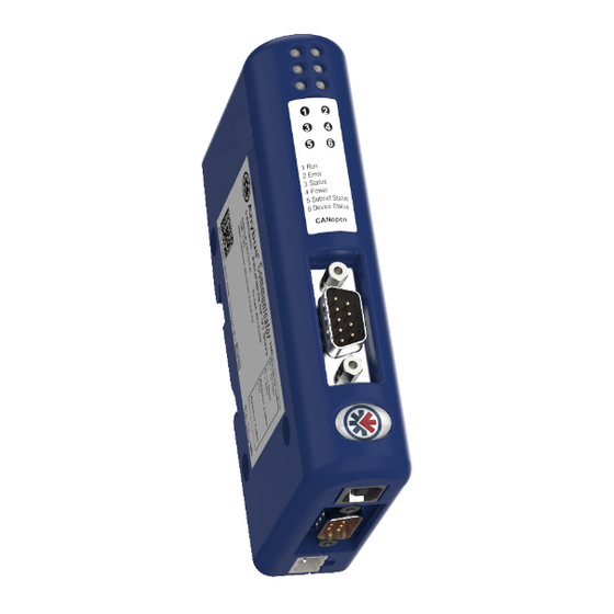
Page 15: Status Leds
Flashing red Transaction error/timeout or subnetwork stopped Fatal error 6 - Device status Power off Alternating Red/Green Invalid or missing configuration Green Operation mode Run Flashing green Operation mode Idle Fatal error Anybus Communicator CAN to CANopen Doc.Id. SCM-1200-121 Doc.Rev. 1.00... -
Page 16: Connectors
The configuration switches are used to set the CANopen node address and baud rate. Normally, these switches are covered by a plastic hatch. Note that the node address can not be changed during runtime, i.e. the Anybus Communicator CAN requires a reset for any changes to have effect. -
Page 17: Usb Connector
• Use 60/75 or 75×C copper (CU) wire only. • The terminal tightening torque must be between 5... 7 lbs-in (0.5... 0.8 Nm) See also... - “Power Supply” on page 42 Anybus Communicator CAN to CANopen Doc.Id. SCM-1200-121 Doc.Rev. 1.00... -
Page 18: Software Installation
Insert the CD and follow the onscreen instructions. If the installation does not start automatically right-click on the CD-drive icon and select Explore. Execute ‘setup.exe’ and follow the onscreen instructions • From website Download and execute the self-extracting .exe file from the HMS website (www.anybus.com). Anybus Communicator CAN to CANopen Doc.Id. SCM-1200-121 Doc.Rev. 1.00... -
Page 19: Getting Started
1. Download the Anybus Configuration Manager from the product pages at www.anybus.com or copy it from the CD that accompanies the product. Install it on your PC. 2. Download the EDS file from the product pages at www.anybus.com or copy it from the CD that accompanies the product. -
Page 20: Can Network Communication
Data on CAN is exchanged using frames. Each frame has a unique identifier for the data it exchanges. The identifier also represents the message priority on the CAN network. The Anybus Communicator CAN supports 11-bit (CAN 2.0A) and 29-bit (CAN 2.0B) identifiers. -
Page 21: Produce And Consume
• Group A group in the Anybus Configuration Manager does not represent any special device on the CAN network. It is a means to structure the transactions that are defined for the Communicator. Each group can be associated with a number of transactions, see below. -
Page 22: Control/Status Word
1 - Bus off Reset CAN If set, the CAN controller has been reset (used when the CAN interface is bus off). complete (Reserved) Operation mode 0 - Idle 1 - Run Anybus Communicator CAN to CANopen Doc.Id. SCM-1200-121 Doc.Rev. 1.00... -
Page 23: Transaction Live List
The latest live list is always available from the Anybus Configuration Managers Diagnostics/Status win- dow, whether the live list is mapped in the input data area or not, see “Diagnostics/Status” on page 38. -
Page 24: General
5. Data Representation on CANopen 5.1 General The Anybus Communicator acts as a slave on the CANopen network. As such, it does not initiate com- munication towards other nodes by itself, but can be read from/written to by a CANopen master. -
Page 25: Memory Layout (Internal Memory Buffer)
For more information about the object dictionary implementation, see “Object Dictionary Implemen- tation” on page 73. 5.3 Memory Layout (Internal Memory Buffer) The I/O sizes specified in the Anybus Configuration Manager correlate to Communicator memory as follows: Example: In this example, the control/status word is disabled and the I/O sizes for the Communicator... - Page 26 2021h, 126 Byte 509 2003h, 124 Byte 510 2003h, 125 2003h, 125 2021h, 127 Byte 511 2003h, 126 2003h, 126 2040h, 127* *The last two bytes are filled up with zeroes Anybus Communicator CAN to CANopen Doc.Id. SCM-1200-121 Doc.Rev. 1.00...
-
Page 27: Chapter 6 Configuration
This file is used by the network configuration tool during network configuration. The latest version of the EDS file for the Anybus Communicator CAN - CANopen interface can be downloaded from the HMS website, ‘www.anybus.com’. -
Page 28: Anybus Configuration Manager
A valid address range is always shown in the information section of the main win- dow. 7.1 Main Window The main window in the Anybus Configuration Manager (ACM) is divided into 4 sections as follows: 1. Pull-down Menus & Toolbar The toolbar provides quick access to frequently used functions. -
Page 29: Pull-Down Menus
Save the current configuration under a new name. • Recent Files Displays a list of recently accessed configurations • Exit Close the Anybus Configuration Manager. Edit This menu features the following entries: • Undo Undo the most recent action. Repeat to undo more actions. •... - Page 30 If a low value is entered, it may affect the performance of the Communi- cator, i.e. the data throughput delay will be longer. b. The Log File contains time stamped versions of the line listener and diagnostic logs. Anybus Communicator CAN to CANopen Doc.Id. SCM-1200-121 Doc.Rev. 1.00...
- Page 31 Upload Configuration This entry uploads a previously downloaded configuration to the Anybus Configuration Manager. • Download Configuration This entry downloads the configuration to the Anybus Commu- nicator CAN. Any previously downloaded configuration will be overwritten. • Set Module Password This option makes it possible to create, change and remove password for a module.
-
Page 32: Basic Settings
During start-up the fieldbus interface of the Communicator is initialized to fit the configuration created in the Anybus Configuration Manager. Optionally, some initialization parameters can be set manually to provide better control over how the data shall be treated by the Communicator. -
Page 33: Communicator Settings
The action in case of a fatal software event is decided by this parameter Parameter Values Comment Action Stay in Safe-State The Communicator will be locked in the safe state Software Reset The software will be reset and the Communicator will be restarted automatically Anybus Communicator CAN to CANopen Doc.Id. SCM-1200-121 Doc.Rev. 1.00... -
Page 34: Subnetwork Settings
- a change from 29 bit to 11 bit identifier will cause the upper 18 bits to be deleted and the lower 11 bits kept. WARNING! This may in some cases cause faulty CAN identifiers. Anybus Communicator CAN to CANopen Doc.Id. SCM-1200-121 Doc.Rev. 1.00... -
Page 35: Groups And Transactions
Note: The transaction live list is always available in the Diagnostics/Status window, even when it is not mapped to the input data area in the memory. Anybus Communicator CAN to CANopen Doc.Id. SCM-1200-121 Doc.Rev. 1.00... -
Page 36: Produce
The transaction will be triggered on a change in this byte. Right click on ‘Produce’ to add a CAN frame to the configuration. For the setup of CAN frames see “Configuration of CAN Frames” on page 33. Anybus Communicator CAN to CANopen Doc.Id. SCM-1200-121 Doc.Rev. 1.00... -
Page 37: Consume
Right click on either ‘Query’ or ‘Response’ to add a new CAN frame. For the setup of CAN frames see “Configuration of CAN Frames” on page 33. Anybus Communicator CAN to CANopen Doc.Id. SCM-1200-121 Doc.Rev. 1.00... -
Page 38: Chapter 10 Configuration Of Can Frames
The Anybus Configuration Manager makes it possible to decide the configuration of the 8 bytes of data that can be included in each frame. The configuration manager automatically allocates memory space in the input and output areas of the Communicator for the data objects that are configured in the frames. -
Page 39: Produce/Query Can Frame
When receiving a message with a constant, the range: 0x0000 - received value will be checked against this value. 0xFFFF) If the values differ, the message will be ignored (little endian). Anybus Communicator CAN to CANopen Doc.Id. SCM-1200-121 Doc.Rev. 1.00... - Page 40 When receiving a message with a limit object, the received value will be checked against the maxi- mum value. If the received value is larger than the maximum value, the message will be ignored. Anybus Communicator CAN to CANopen Doc.Id. SCM-1200-121 Doc.Rev. 1.00...
-
Page 41: Chapter 11 Anybus Configuration Manager Tools
Chapter 11 11. Anybus Configuration Manager Tools The Anybus Configuration Manager (ACM) gives access to different tools for monitoring and control- ling the module and the CAN subnetwork: • Monitor/Modify • CAN Line Listener • Diagnostics/Status • Address Overview 11.1 Monitor/Modify Selecting this option in the Tools menu opens this window, where the data areas of the transactions can be monitored. -
Page 42: Can Line Listener
Anybus Configuration Manager Tools 37 11.2 CAN Line Listener The CAN Line Listener gives the opportunity to log the traffic on the CAN network. Any log can be saved for later use. The 5000 latest frames are logged. This is done continuously, or it is possible to stop logging after 5000 frames from a defined time. -
Page 43: Address Overview
Anybus Configuration Manager Tools 38 11.3 Address Overview The Address Overview tool shows the usage of the different memory areas in the module. It gives an easy view of any collisions of data that are present in the different memory areas. If needed, the memory location for the data of one transaction at a time, can be shown. - Page 44 Live List”. Fatal Error Information If the Communicator is subject to a fatal error, this information is used by HMS support when troubleshooting the module. Please contact HMS support at www.anybus.com if a fatal error occurs. Anybus Communicator CAN to CANopen Doc.Id.
-
Page 45: Chapter 12 Online
Chapter 12 12. Online The entries in the Online menu are used to find and connect to a Anybus Communicator CAN module and to administer the module: • Select Connection • Connect/Disconnect • Upload Configuration • Download Configuration • Set Module Password Connect the Communicator that is to be configured to your PC using the included USB cord. - Page 46 A password can be set either for download- ing a configuration, uploading a configura- tion or for both. If the Password Type field is empty, no pass- word is available, or the password is disabled. Anybus Communicator CAN to CANopen Doc.Id. SCM-1200-121 Doc.Rev. 1.00...
-
Page 47: Appendix A Technical Specification
Celsius (Test performed according to IEC-60068-2-1 and IEC 60068-2-2.) A.3.2 Relative Humidity The product is designed for a relative humidity of 5 to 95% non-condensing. Test performed according to IEC 60068-2-30. Anybus Communicator CAN to CANopen Doc.Id. SCM-1200-121 Doc.Rev. 1.00... -
Page 48: Emc (Ce) Compliance
EMC compliance testing has been conducted according to the Electromagnetic Compatibility Directive 2004/108/EC. For more information please consult the EMC compliance document, see product/sup- port pages for Anybus Communicator CAN to CANopen (slave) at www.anybus.com. Anybus Communicator CAN to CANopen Doc.Id. -
Page 49: Chapter B Configuration Example
Chapter B B. Configuration Example This appendix gives an example of the configuration of an Anybus Communicator CAN to collect data from a tempera- Fieldbus Control System ture sensor and to control and monitor a motor. (e.g a PLC) 1. Start the Anybus Configuration Manager - Communi- cator CAN (ACM). - Page 50 - Finally add one Consume transaction to collect the data cyclically from the temperature sen- sor. Rename the transaction to ‘Temperature’ and set Update Mode to Cyclically. - Leave the rest of the parameters at default values. Anybus Communicator CAN to CANopen Doc.Id. SCM-1200-121 Doc.Rev. 1.00...
- Page 51 - Add one Consume transaction (‘Motor Status’) to collect status cyclically from the motor. - Finally add a Produce transaction (‘Speed’) to be able to change the speed of the motor. Anybus Communicator CAN to CANopen Doc.Id. SCM-1200-121 Doc.Rev. 1.00...
- Page 52 12. Download the configuration to the Communicator using the USB connection. Remove the USB cable when finished A configuration can be saved at any time and opened at a later time for editing. Once it is valid it can be downloaded to the Anybus Communicator CAN. Anybus Communicator CAN to CANopen Doc.Id. SCM-1200-121...
-
Page 53: Appendix C Canopen Object Dictionary
Node ID + Heartbeat Time. Time Value must be a multiple of 1ms. 1017h Producer Heart- Producer Heartbeat beat Time Time 1018h Identity object Number of entries Vendor ID Product Code Revision Number Serial Number Anybus Communicator CAN to CANopen Doc.Id. SCM-1200-121 Doc.Rev. 1.00... - Page 54 1A4Fh Mapped object #1 Mapped object #2 Mapped object #3 Mapped object #4 Mapped object #5 Mapped object #6 Mapped object #7 Mapped object #8 a. Relevant only for communication parameters Anybus Communicator CAN to CANopen Doc.Id. SCM-1200-121 Doc.Rev. 1.00...
-
Page 55: Manufacturer Specific Objects
Input area word #64 Input area word #65 Input area word #127 2023h Input area No. of entries Input area word #192 Input area word #193 Input area word #255 2024h (reserved) 202Fh Anybus Communicator CAN to CANopen Doc.Id. SCM-1200-121 Doc.Rev. 1.00... -
Page 56: Input Buffer, Double Word Access
Output area byte #128 Output area byte #129 Output area byte #255 2103h Output area No. of entries Output area byte #384 Output area byte #385 Output area byte #511 2104h (reserved) 210Fh Anybus Communicator CAN to CANopen Doc.Id. SCM-1200-121 Doc.Rev. 1.00... -
Page 57: Output Buffer, Word Access
Output area dword #32 Output area dword #33 Output area dword #63 2143h Output area No. of entries Output area dword #96 Output area dword #97 Output area dword #127 2144h (reserved) 214Fh Anybus Communicator CAN to CANopen Doc.Id. SCM-1200-121 Doc.Rev. 1.00... -
Page 58: Anybus Status & Diagnostics
CANopen Object Dictionary 53 C.2.7 Anybus Status & Diagnostics Index Object Name Sub-Index Type Access Notes 2200h Bus State Indicator Reflects the actual state of the bus. 1: Bus running 2: Bus error 2205h Module State Indicator Reflects the state of the slave interface:...
Need help?
Do you have a question about the Communicator - CANopen and is the answer not in the manual?
Questions and answers