Advertisement
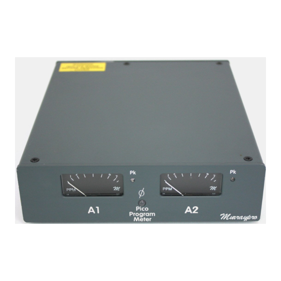
Murraypro
The following procedure defines the processes required to
perform the alignment of the "Pico" correctly.
The procedure described below should only be performed on Pico units that have been
PAT tested, and declared safe for subsequent use. This status is confirmed by affixing a
printed PAT report, with wide transparent tape to the underside of the Pico.
The following pieces of equipment, and cables will be required.
1)
Audio oscillator with dual, balanced OP, and associated PHASE reversal switch on
one channel only.
2)
Precision audio meter capable of measuring audio levels to 0.1dB, or better.
3)
4 off, XLR3 male to female cables.
4)
A second Pico, with audio A1 & A2 input wiring phase confirmed as correct.
A)
Using an "XLR3-F to XLR3-M" lead, connect the Audio Meter to output 1 of the
Audio oscillator, and then to output 2. Both outputs of the oscillator should be producing an
identical output level, which must be adjusted to generate 0dBU precisely, "ie an output of
0.775V RMS).
This 0dBU is the standard reference level from which ALL other measurements are
made, as a positive or negative offset. Correct setting, and maintenance, of this level is
VITAL.
B)
Connect the two outputs of the audio oscillator to the two female XLR3s on the Pico
rear panel. Ensure that the PHASE reversal switch on the generator is in the "normal"
(non-inverted) condition.
C)
Ensure that the Audio Oscillator is set to "SINE", and generating 1Khz, nominal.
All adjustments that require accurate meter setting MUST be performed with "normal"
viewing, to remove any possible parallax error. A small mirror may be found useful to assist
with obtaining a convenient viewing angle.
D)
With no power applied to the Pico, check that the mechanical zero of the two meters
are correct. Any pointer alignment error is corrected by adjustment of the nylon screw on the
respective meter rear.
E)
Apply mains power and, whilst the electronics are stabilising (allow 5 minutes before
making any adjustment) check that the white LEDs are all illuminated, and that the scale
illumination is reasonably consistent with no obvious hot spots. Correct any LED
misalignment before proceeding. Do NOT be tempted to adjust the LED's positioning with
power applied, it will be very easy to short circuit the LED leads to the case and to destroy
them.
F)
Check that the PHASE LED is extinguished when no signal is applied to either input,
ie "stereo silence".
G)
REMOVE test link "LK1" at the front of the main board and adjust the 2 individual
meter sensitivity controls R47 and R48 to give a deflection of exactly "4" on each meter.
Replace the link "LK1". Note the PICO generates an internal calibration signal for this
particular parameter, and NO EXTERNAL INPUT SIGNALS ARE REQUIRED. Be aware
that this is NOT the procedure for setting PICO gain.
Pico PPM Alignment V2.1
Advertisement
Table of Contents

Related Manuals for Murraypro Pico PPM


Summary of Contents for Murraypro Pico PPM
- Page 1 Murraypro Pico PPM Alignment V2.1 The following procedure defines the processes required to perform the alignment of the “Pico” correctly. The procedure described below should only be performed on Pico units that have been PAT tested, and declared safe for subsequent use. This status is confirmed by affixing a printed PAT report, with wide transparent tape to the underside of the Pico.
- Page 2 Murraypro Pico PPM Alignment V2.1 !!!!!!!!!!!!!!!!!!!!!!!!!!!!!!!!!!!!!!!!!!!!!!!!!!!!!!!!!!!!!!!!!!!!!!!!!!!!!!!!!!!!!!!!!!!!!!!!!!!!!!!!!!!!!! SETTING the PICO’s signal gain. With the 0dBU reference tones applied to the PICO’s XLR inputs, adjust input sensitivity presets R37 and R38 to give exactly “4” again on each meter. These are THE ONLY controls that should adjusted to normalise the PICO’s signal gain.
Need help?
Do you have a question about the Pico PPM and is the answer not in the manual?
Questions and answers