Table of Contents
Advertisement
Quick Links
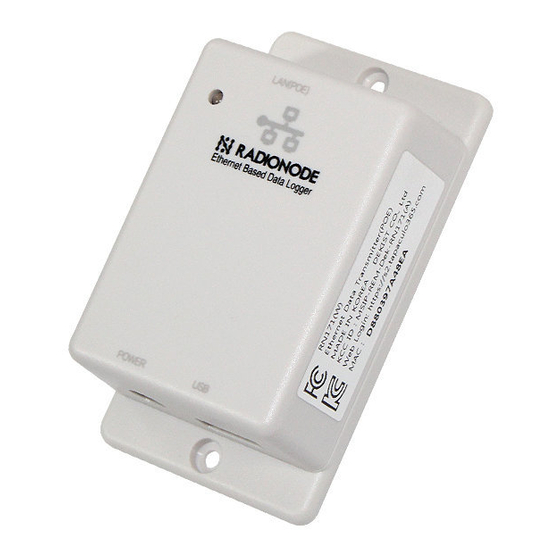
RN171
RADIONODE Sensor Data Transmitter Device
(via Ethernet)
✓
POE(Power Over Ethernet)-supported
✓
Temperature/Humidity, Thermocouple(T/K
Type), PT100, 4-20mA, Gas
✓
For making phone calls alert/sending SMS
alert
✓
Supports cloud monitoring(Tapaculo365)
✓
Supports MODBUS TCP/HTTP data
transmission
✓
2CH LED display on the front
✓
Sound buzzer inside
Product Overview
The RN171 Ethernet data transmission device delivers
the data from the UA sensor products to a remote
receiver through the Ethernet.
The remote receiver refers to the PCs where the
Tapaculo software is installed, a cloud monitoring
service (Tapaculo®365), or the web server developed
by the user.
The RN171 device is equipped with a display
Purpose
• Gathering sensor information
through the network
• Establishment of an integrated
control system
• Establishing an industrial alarm
system
©2019 DEKIST Co., Ltd.
on the front to show the data, and with a buzzer
to sound the alarm when the limit value is
exceeded.
The system also provides a cloud monitoring
service, which is one of the advanced features
of the system (Tapaculo ® 3 65).
Using this service, it is possible to send an
emergency SMS/telephone alarm or schedule
to send e-mail reports.
Application
•Food storage (freezer, refrigerated)
• Bio laboratory
• Building energy use monitoring
• Medicine storage
• Semiconductor production line
www.radionode365.com
Rev. 1.9
Advertisement
Table of Contents

Related Manuals for Radionode RN171


Summary of Contents for Radionode RN171
- Page 1 (Tapaculo®365), or the web server developed of the system (Tapaculo ® 3 65). by the user. Using this service, it is possible to send an The RN171 device is equipped with a display emergency SMS/telephone alarm or schedule to send e-mail reports. Purpose Application •...
-
Page 2: Block Diagram
Order number Block diagram • Model : RN171 1.Specification RN171 Product Specifications Size H25 * W50 * D70 (mm) Communication Ethernet 100Mbps protocol Power POE 48V, IEEE802.3af/at, HTTP RADIONODE PROTOCOL consumption DC6V, 1.9W transmission protocol HTTP GET Buzzer Threshold alarm... - Page 3 2. Components Model Components RN171-W RN171W(1EA), USB Extension Cable(1EA), USB gender(1EA) 3. Products Caution Warning In case of use on a device that impacts human life or property, be sure to attach a safety device in double. It can result in serious loss such as fire, personal injury or property damage.
-
Page 4: How To Operate
4.1 Data logging on the local PC RN171 is a suitable product for establishing an integrated monitoring server through the Ethernet. It is used to transmit the data gathered by UA 10 or UA11, etc. The image above shows an example of a configuration of the monitoring server through the intranet, without being connected to the internet. - Page 5 Through the internet, it is possible to use the product to gather information from other devices located in a remote place. Each RN171 device will do with a private IP from the internet router. No separate public IP is necessary. Tapaculo365.com supports data gathering. It provides free accounts with which you can use up to 20 data channels.
-
Page 6: Console Menu
Using the USB cable, you can access the configuration menu through the PC. While the POE is not powered on, use the USB cable to connect the RN171 unit to a PC. When power is supplied through the USB cable, the device automatically operates in the reconfiguration console mode. -
Page 7: Network Setting
----------------------------------------- RADIONODE RN171 SERIES SYSTEM INFORMAION PRODUCT MODEL : RN171W HTTP INTERVAL : 5 Min. DATA DESTINATION : TAPACULO365.COM ETHERNET MAC : D880393E05ED VIRTUAL MAC : D880393E05ED CURRENT IP ADDR : 0.0.0.0 MODBUS TCP PORT : 502 BUILD VERSION : Mar 31 2016... -
Page 8: System Configuration
D. Input the Min value of Channel 2. E. Input the Max value of Channel 2. F. C hoose whether to use the internal buzzer in the RN171 or not to (SOUND ON/OFF). G. Turn the remote alarm lamps (siren) ON/OFF. - Page 9 5.4 HTTP Request setting [4.HTTP DESTINATION SETUP MENU.] A.Set HTTP Host URL [ 100.10.10.112 ] B.Set HTTP Host Port [ 80 ] C.Set HTTP NMAC [ 0000D880393E05ED ] D.Set HTTP DATAIN File[/test.jsp] Q.Quit. A. Input the URL of the server that receives the information through the HTTP protocol. B.
- Page 10 An RN171 device is equipped with three indicative devices (LED, CH1 DISPLAY, and CH2 DISPLAY). LED may operate in two colors. In most cases, you will see a green light, which means that the equipment is functioning normally. When data is transmitted or an alarm is sounded, the lamp will turn red. The CH1/CH2 DISPLAY normally indicates the data value.
-
Page 11: Telnet(Command)
This mode is used to internal memory. change the settings. HoLd 0000 CONF 0005 7. Telnet(command) While the RN171 device is in operation, the user may access the device through Telnet. After accessing the ©2019 DEKIST Co., Ltd. www.radionode365.com Rev. 1.9... - Page 12 Telnet, input the AT command to view or change the settings of the RN171 device. The default port number is 23. AT Command Contents Answer “ATDC DATA ATDC Checks the current CH1 and CH2 9.11 , values.
- Page 13 SERVER-ADDRESS] ? g wid = 0004a316d728& m odel = RN171& i nterval = 300& i paddr = 192.168.0.31& u tc = 1459249 __device = 00000004a316d728& n odeid = 00000004a316d728& l qi = 255& c hild = 0& n odetype = 2&...
- Page 14 9. MODBUS TCP Protocol Definition It is possible to read the currently measured data from RN171 through MODBUS TCP communication. The data is updated to “ H OLDING REGISTER ” in real time. The 4 BYTE FLOATING POINT and 2 BYTE UNSIGNED INT formats are supported.
-
Page 15: Installation Of The Device
If the RN171/172 products can be connected to the internet, the field data can be monitored from a remote place with ease. 10.1 Installation of the device Connect the RN171/172 devices to the power source and proceed with the establishment of an internet connection. - Page 16 Press the Add a Device button to open a pop-up window. Then input the descriptive text on the device. Then press S ave to complete the addition of the device. The device will play a melody to indicate that the registration process has been completed.
- Page 17 Click the Add Channel button. A pop-up window will appear. Input the channel name and select the unit to complete the registration. Once the channel name is registered, make proper preparations so that the report, dashboard, or detail view screen will show the relevant name. 10.4 Use the web service After completing the channel registration, you may use the various features, such as the report, dashboard, or alarm setting, of ...
- Page 18 Ex) Reports 11. How to Use the Tapaculo Lite PC Bundle Software 11.1 Install Tapaculo Lite in your PC Install Tapaculo Lite( w ww.radionode365.com > Support > Software Download > Tapaculo Lite) on a Windows-operated PC and launch the program. Click "...
- Page 19 11.2 Add a new device to Tapaculo Lite Access the Create Project menu, and you will see the RN171 devices detected as Broadcasting. Of these, select the device whose data you wish to save. Select the t ime interval for saving the data from among 1 sec, 5 secs, 10 secs, 1 minute, 5 minutes, and 10 minutes.
- Page 20 13. Question and Service ● Free repair service within one year. ● Company : DEKIST Co., Ltd ● Paid repair service after one year. ● Phone : 070-7529-4359 ● : 031-8039-4400 ● Email : master@dekist.com 14. Software Download You can download the relevant software at w ww.radionode365.com...
Need help?
Do you have a question about the RN171 and is the answer not in the manual?
Questions and answers