Advertisement
Quick Links
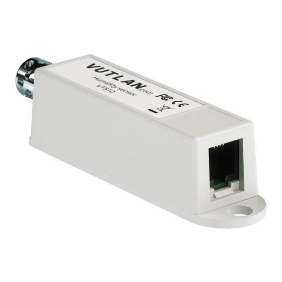
VT510 / Humidity sensor (v2)
Documentation page:
https://vutlan.atlassian.net/wiki/spaces/DEN/pages/1841463297/VT510+Humidity+sensor+v2
Product page:
https://vutlan.com/analog-sensors/16-vt510-humidity.html
Function and purpose
The sensor is needed for the measurement of relative humidity 0-95% indoors with a relative accuracy of 3%RH.
Technical specifications
VT510
Product dimensions
Power Consumption
Operating temperature
Operating humidity
Storage temperature
Storage humidity
Mounting possibilities
(Length, Width, Height) 60×18×18 mm
60 mW
-40° C to +100° C
0 to 95 %
-40° C to +100° C
0 to 95 %
Desktop and Wall mount
Advertisement

Related Manuals for Vutlan VT510

Summary of Contents for Vutlan VT510
- Page 1 VT510 / Humidity sensor (v2) Documentation page: https://vutlan.atlassian.net/wiki/spaces/DEN/pages/1841463297/VT510+Humidity+sensor+v2 Product page: https://vutlan.com/analog-sensors/16-vt510-humidity.html Function and purpose The sensor is needed for the measurement of relative humidity 0-95% indoors with a relative accuracy of 3%RH. Technical specifications VT510 Product dimensions (Length, Width, Height) 60×18×18 mm...
- Page 2 Max. distance from the 150 m unit Manufactured in (country) Manufactured in Slovak Republic, E.U. HS Code 9025 11 800 Special Features Accuracy 3% RH Inputs terminals RJ-12 / RJ-11 Certifications GPSD, ROHS, CE, Quality certificate Package includes Package specifications Feature Description Packaging weight...
-
Page 3: Analog Sensors Connection
Sticker Drawing Connecting vibration sensor The sensor uses a standard Vutlan analog RJS5 RJ11 sensor cable for connecting to the monitoring unit. Analog sensor connection Analog sensors connection Connect the analog sensor by a supplied RJ-11 (6P4C) cable to any analog port "A1 .. A8" or "Sensor" port. The determination... - Page 4 If strong electromagnetic interference is present, we recommend using 3-pair cable CAN FTP for sensor connection! 6P4C RJ11 cable wiring / pinouts 1- Yellow, 2- Green, 3- Red, 4 - Black Colors are true for this telephone cable. Both ends match the colors and pinouts (identical). Please refer to the RJ connectors comparison table:...
- Page 5 Daisy chain connection Some of the analog sensors can be connected in a daisy chain. Please refer to the article "Chain connection of analog sensors". Extending the number of analog sensors Using CAN extension " VT408 / Sensor extension unit "...
- Page 6 Installation using a sticker and a bracket Option 1. There's a round bump at the bottom of the plastic enclosure of the sensor. It is used for fastening when the sensor is mounted together with the on walls using a screw. In the current example, it is not needed. If you are planning to mount a device differently, do not follow this step.
- Page 7 Option 2. a) Stick the mounting sensor to the surface using the sticker. b) Stick a sensor to the surface using a screw. Option 3. Mount the sensor to the surface using a mounting bracket. The mounting bracket and the sensor can be either attached by the stickers or together with screws and nuts.
- Page 8 Connecting the sensor Sensor configurations To configure a sensor, go to "Main menu" >> "System tree" and click on the sensor element in the tree. A modal window with sensor properties will pop up. Change the needed settings and click "OK" or "Apply" at the bottom of the "Properties" window.
- Page 9 All sensors include: Name Name is given by the system automatically. You can change it to anything you want. System ID of the element. Type Example: temperature, humidity, vibration. Class Examples: analog, CAN, switch, discrete. Hardware port The external port number on the device panel to which the sensor is connected (if the sensor is external).
- Page 10 On the picture above, "Current value" equals 41.0 and is represented by the small triangle. Currently the triangle is green because it is situated in an "Normal" range. Hence the sensor says that "Current state" is "Normal". This value is used by the system "Logic schemes"...
- Page 11 Each fuel tank has it's own formula for volume vs height. Please see this useful resource for finding out such a formula. https://www.calculatorsoup.com/calculators/construction/tank.php In this can, You need to use non-linear formula. Tuning the sensor value Copyright: Vutlan s.r.o. (LLC) Remote Infrastructure Monitoring and Control...
- Page 12 43 ul.Svornosti, 821 06 Bratislava, Slovak Republic www.vutlan.com...
Need help?
Do you have a question about the VT510 and is the answer not in the manual?
Questions and answers