Table of Contents
Advertisement
Quick Links
®
PORTFOLIO
and PORTFOLIO & Design
are trademarks or registered trademarks of
LF, LLC. All rights reserved.
Purchase Date
Questions, problems, missing parts? Before returning to your retailer, call our customer
service department at 1-800-643-0067, 8 a.m. - 8 p.m., EST, Monday - Sunday. You could
also contact us at partsplus@lowes.com or visit www.lowespartsplus.com.
SM20441
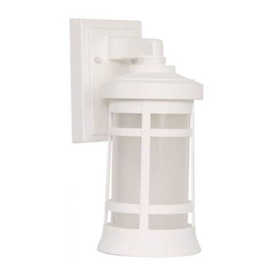
OUTDOOR WALL LANTERN
TM
1
ITEM #2062003
2602004
MODEL #WL132MBK
WL132WW
Français p. 11
Español p. 21
ATTACH YOUR RECEIPT HERE
JOIGNEZ VOTRE REÇU ICI
ADJUNTE SU RECIBO AQUÍ
For Wet
Location
E87731
Advertisement
Table of Contents

Subscribe to Our Youtube Channel
Related Manuals for Portfolio WL132MBK


Summary of Contents for Portfolio WL132MBK
- Page 1 ITEM #2062003 2602004 OUTDOOR WALL LANTERN ® PORTFOLIO and PORTFOLIO & Design are trademarks or registered trademarks of MODEL #WL132MBK LF, LLC. All rights reserved. WL132WW Français p. 11 Español p. 21 ATTACH YOUR RECEIPT HERE JOIGNEZ VOTRE REÇU ICI ADJUNTE SU RECIBO AQUÍ...
-
Page 2: Table Of Contents
TABLE OF CONTENTS Package Contents ....................... 2 Hardware Contents ......................3 Safety Information ........................ 3 Preparation .......................... 5 Assembly Instructions ......................5 Care and Maintenance ....................... 10 Troubleshooting........................10 Warranty ..........................10 PACKAGE CONTENTS PART DESCRIPTION QUANTITY Fixture... -
Page 3: Hardware Contents
HARDWARE CONTENTS (shown actual size) Wire Connector Qty. 3 Fixture Screw Qty. 2 Mounting Decorative Plate (preassembled to (CC)) Qty. 2 Qty. 1 Qty. 2 SAFETY INFORMATION READ AND SAVE THESE INSTRUCTIONS. DANGER • For your protection and safety, carefully read and understand the information provided in this manual completely before attempting to assemble, install or operate this product. - Page 4 SAFETY INFORMATION DANGER • DO NOT connect the bare or green insulation fixture ground wire to the black (HOT) current-carrying wire or the white neutral house wire. Connection of the bare or green fixture ground wire to the black or white house wires may cause metal parts of the fixture to carry electrical currents.
-
Page 5: Preparation
PREPARATION Before beginning assembly of product, make sure all parts are present. Compare parts with package contents list and hardware contents list. If any part is missing or damaged, do not attempt to install, operate or assemble the product. Estimated Assembly Time: 30 minutes Tools Required for Assembly (not included): Flathead Screwdriver, Phillips Screwdriver, Wire Strippers, Pliers, Wire Cutters, Safety Glasses, Stepladder, Electrical Tape, Silicone Weather Sealant (and tool to apply sealant) - Page 6 ASSEMBLY INSTRUCTIONS Insert fixture screws (CC) completely into mounting plate (AA), one directly across from the other. Attach one nut (EE) to each fixture screw (CC). [Adjustment will be made later.] Hardware Used Mounting Plate [not shown actual size] Fixture Screw Attach mounting plate (AA) to outlet box (not included) using the existing outlet box screws and washers.
- Page 7 ASSEMBLY INSTRUCTIONS Temporarily place fixture (A) over mounting plate Outlet Box (AA) to determine amount of adjustment necessary for fixture screws (CC). NOTE: Fixture screws (CC) should come through holes in fixture (A) just enough so decorative nuts (DD) fit flush against fixture (A) when mounted.
- Page 8 ASSEMBLY INSTRUCTIONS 6b. Connect BARE/GREEN ground wire from outlet box to BARE wire from fixture (A) using wire WHITE BLACK connector (BB). Connect WHITE wire from fixture (A) to WHITE wire from outlet box using wire connector (BB). Connect BLACK wire from fixture (A) to BLACK wire from outlet box using wire connector (BB).
- Page 9 ASSEMBLY INSTRUCTIONS 8. Align holes in fixture (A) with fixture screws (CC) on mounting plate (AA) and push fixture (A) toward wall. Attach fixture (A) to mounting plate (AA) using the decorative nuts (DD). Hardware Used Mounting Plate [not shown actual size] Fixture Screw Decorative Nut 9.
-
Page 10: Care And Maintenance
ASSEMBLY INSTRUCTIONS 11. After completing installation, caulk mounting surface of fixture (A) with silicone weather sealant (not included). WARNING: Failure to caulk fixture mounting surface with silicone weather sealant may result in water damage in outlet box, which may cause electrical malfunction or electrical shock.
Need help?
Do you have a question about the WL132MBK and is the answer not in the manual?
Questions and answers