Table of Contents
Advertisement
Quick Links
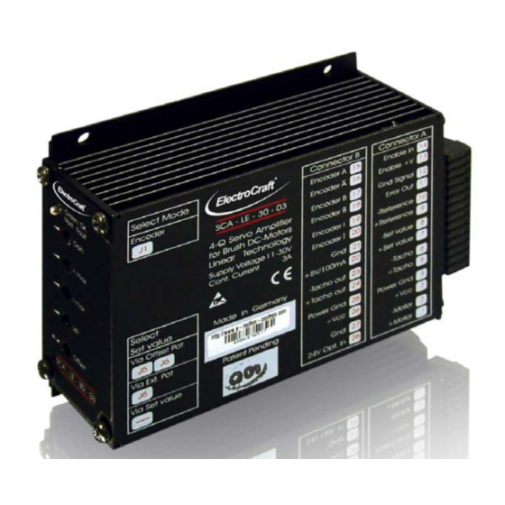
User Manual SCA-LE-30-03
4–Q Linear Servo – 03 A
SCA-LE-30-03
•
Servo amplifier in a rugged aluminium housing
•
Different methods of mounting for fast installation
•
Inputs and outputs via screw terminals
•
Operation mode setting with jumpers
•
User adjustable current limit
•
Wide range supply voltage between +11 and +30 VDC for different kinds of DC-
power supplies
•
Protected against overtemperature and over-current
•
Linear amplifier
•
Continuous current up to 6 A
Basic drive description: The SCA-LE-30-03 servo amplifiers are designed to drive DC
brush type motors. They require a single DC power supply for operation. The drives are to
be used with a single motor. They have the functionality to operate as an independent
speed control or high performance servo. The drives are protected against short circuits,
under voltage, over temperature, and over current. It has multiple modes of operation and
serves as a reliable choice for your motion control needs.
®
ElectroCraft
E-Mail: info@electrocraft.com
For Brush-Commutated DC Motors up to 75 W
www.electrocraft.com
1
May 2009
Advertisement
Table of Contents

Subscribe to Our Youtube Channel
Related Manuals for ElectroCraft SCA-LE-30-03


Summary of Contents for ElectroCraft SCA-LE-30-03
- Page 1 • Continuous current up to 6 A Basic drive description: The SCA-LE-30-03 servo amplifiers are designed to drive DC brush type motors. They require a single DC power supply for operation. The drives are to be used with a single motor. They have the functionality to operate as an independent speed control or high performance servo.
-
Page 2: Table Of Contents
User Manual SCA-LE-30-03 Table of Contents Safety & Installation ..............3 Specifications: ................4 Drive Overview ................6 Wiring ..................10 Explanation of Terminals, Dip Switches, & Potentiometers .. 13 Glossary ..................17 Description of Inputs and Outputs .......... 24 Basic Troubleshooting ............. -
Page 3: Safety & Installation
Improper wiring could cause a “motor run away” condition, and cause serious injury or damage to the machine and persona Before starting installation of the SCA-LE-30-03, be sure that main power is disconnected. After powering the drive it should not be touched by hand or risk shock. -
Page 4: Specifications
User Manual SCA-LE-30-03 Specifications: Electrical Data Power Supply Voltage +11 to +30 VDC (Residual ripple <5 %) (The lower limit monitored integrated undervoltage trip) WARNING: Do not exceed 70V. Overvoltage will damage the drive. Nominal Current Maximum Power (only achievable with 75 W additional heatsink &... - Page 5 User Manual SCA-LE-30-03 Mechanical Data Mechanical Dimensions L x W x H 121 x 100 x 40 mm Weight 380 g Mounting M3 screws or Din Rail Mounting Ambient Conditions Operation Temperature -10 to +45 Storage Temperature -40 to +85...
-
Page 6: Drive Overview
User Manual SCA-LE-30-03 Drive Overview Block Diagram ® ElectroCraft E-Mail: info@electrocraft.com www.electrocraft.com May 2009... - Page 7 User Manual SCA-LE-30-03 Input & Output Schematics ® ElectroCraft E-Mail: info@electrocraft.com www.electrocraft.com May 2009...
- Page 8 User Manual SCA-LE-30-03 Control Elements Operation Modes Encoder Mode At encoder mode feedback information is coming from the encoder signals. The encoder is mounted at the motor. The speed regulation has got a high performance at each load condition and qualified for each application to control exactly the speed of a system especially for low speed application.
- Page 9 User Manual SCA-LE-30-03 Tacho Mode In the tacho mode the feedback information is coming as a voltage signal from a tacho mounted at the motor. The speed regulation is very good at each load condition and qualified for each application to control exactly the speed of a system.
-
Page 10: Wiring
User Manual SCA-LE-30-03 Wiring According to the safety directives, a correct cable selection is mandatory. Regular inspection is advisable. Damaged, burned or kinked items have immediately to be exchanged. Power (+Vcc - Power GND) • Normally no shielding required. •... - Page 11 User Manual SCA-LE-30-03 4.1 Wiring Example I – Encoder Mode ® ElectroCraft E-Mail: info@electrocraft.com www.electrocraft.com May 2009...
- Page 12 User Manual SCA-LE-30-03 4.1.1 Setting of the Jumpers Mode Set Value via Encoder Control Offset - external 1,5 kHz potentiometer potentiometer external voltage Note: Advanced information’s about the jumpers refer chapter 5.3. 4.2.2. Adjustment procedure for Encoder mode 1. Presetting of the jumpers J7 –J12 refer chapter 5.3.
-
Page 13: Explanation Of Terminals, Dip Switches, & Potentiometers
User Manual SCA-LE-30-03 Explanation of Terminals, Dip Switches, & Potentiometers 5.1 Terminals Terminal Label Description Pin 1 & 2 connect to motor. Pin 3 & 4 connect to power supply. Pin 5 & 6 input tacho. Pin 7 & 8 input set value. - Page 14 User Manual SCA-LE-30-03 5.2 Potentiometers Potentiometer Function Turning to the Left Turning to the Right (ccw) (cw) Gain Gain Factor lowered Factor raised n max Definition of max. number Value is decreased Value is increased of revolutions Set value for max. current...
- Page 15 User Manual SCA-LE-30-03 5.3 Jumpers Max. Encoder Input Frequency Open Open Open Open Open 600 kHz Open Open Open Open 300 kHz Open Open Open Open Open Open 150 kHz Open Open Open Open 75 kHz Open Open Open 60 kHz...
- Page 16 User Manual SCA-LE-30-03 Function Mode Open Open Speed Control by Voltage Open Speed Control by IxR Open Open Open Torque Control Open Open Open Speed Control by Tacho Methods of entering the set value (refer chapter 7.3) Open Open External selection using a voltage (0 to 10 VDC) between XA/7 and XA/8.
-
Page 17: Glossary
User Manual SCA-LE-30-03 Glossary Offset There are two distinct functions for the Offset-Potentiometer: 1. Levelling the position at which the motor stands still. 2. Selection of the Set Value. This task requires setting jumper J5 and J6. In any mode, this feature is available and offers the possibility of a quick functional test. - Page 18 User Manual SCA-LE-30-03 I max The following action requires the motor to be operated with maximum load. The motor current may be measured e.g. using current probe with effective value display, or by means of an ammeter located in the motor line.
- Page 19 User Manual SCA-LE-30-03 Torque mode In this mode the driver controls only the current into the motor. The speed of the motor depends on the load because only the output force of the motor is regulated. Voltage Mode In the voltage mode the drive is watching the output voltage as a feedback voltage.
- Page 20 User Manual SCA-LE-30-03 Closed loop This is broadly applied term, relating to any system in which the output is measured and compared to the input. The output is then adjusted to reach the desired condition. In motion control, the term typically describes a system utilizing a velocity and/or position transducer to generate correction signals in relation to desired parameters.
- Page 21 User Manual SCA-LE-30-03 Driver Is the electronics which convert step and direction inputs to high power currents and voltages to drive a step motor. The step motor driver is analogous to the servomotor amplifier's logic. Encoder Is a feedback device which converts mechanical motion into electronic signals. The most commonly used, rotary encoders, output digital pulses corresponding to incremental angular motion.
- Page 22 User Manual SCA-LE-30-03 Open-loop A system in which there is no feedback. Motor motion is expected to faithfully follow the input command. Stepping motor systems are an example of open-loop control. Pulse Width Modulation (PWM) 1. A PWM controller (amplifier) switches DC supply voltage on and off at fixed frequencies.
- Page 23 User Manual SCA-LE-30-03 Thermal protection A thermal sensing device mounted to the motor to protect it from overheating. This is accomplished by disconnecting the motor phases from the drive in an over temperature condition. Torque Is a measure of angular force which produces rotational motion. This force is defined by a linear force multiplied by a radius;...
-
Page 24: Description Of Inputs And Outputs
User Manual SCA-LE-30-03 Description of Inputs and Outputs Digital Inputs Enable In: Activating or Disabling the Output Stage If the Enable In input is at GND potential or not wired at all, the output stage remains in the locked state. The motor stands still or slow down without brake. To reactivate the output stage, a voltage signal >8 V to the Enable In input XA/14 is necessary. - Page 25 User Manual SCA-LE-30-03 Two channels (A and B) are required for the working, a third channel (I) can be connected but it is not needed. The drive can work with single ended signals, with differential signals or with line drivers corresponding to the RS422 standard.
- Page 26 User Manual SCA-LE-30-03 Analog Inputs +Set value –Set value: Inputs for Set Value An external +10/-10 V analog signal for speed or for current is entered using +Set value and –Set value inputs. If the effective voltage is 0V, the motor stops. If the effective voltage is positive, the motor moves in one direction.
- Page 27 User Manual SCA-LE-30-03 +Tacho –Tacho: Analog Tachometer Feed Back The +Tacho and –Tacho inputs are transmit an analog set value for the number of revolutions from a tachometer coupled to the motor, back to the servo amplifier. This feature improves the accuracy of speed control, stable even in cases of a large load change. The input is given in form of a differential amplifier.
-
Page 28: Basic Troubleshooting
User Manual SCA-LE-30-03 Basic Troubleshooting The servo amplifier has included some different protective functions. Under voltage and over temperature are monitored and shown with the LED’s at the front side. Important: The motor starts after the failure is eliminated. Motor oscillates •... -
Page 29: Accessories & Options
User Manual SCA-LE-30-03 No motion even though enable is on • Check power supply and the wiring. • Overheating protection is active. Overtemperature • Use an additional heatsink (see accessories). • Reset the amplifier. Note: Beware that the maximal working temperature of 80°C in the driver is not reached;... -
Page 30: Warranties & Disclaimers
• Contents are subject to change without notice. • Electrocraft will not be liable in any way for direct, indirect, incidental, or consequential damages caused by the use of this product or document. • Per Electrocraft’s Terms & Conditions, the user of Electrocraft’s accepts all responsibility and risks involved with applying this product into their machinery and indemnifies Electrocraft against all damages. -
Page 31: Dimensions
User Manual SCA-LE-30-03 11. Dimensions All dimensions in mm. ® ElectroCraft E-Mail: info@electrocraft.com www.electrocraft.com May 2009... -
Page 32: Mounting Din Rail Adapter
User Manual SCA-LE-30-03 12. Mounting Din rail adapter 4 x M4x6 SCA-LE-30-03_E09 Subject to change without prior notice. ® ElectroCraft E-Mail: info@electrocraft.com www.electrocraft.com May 2009...
Need help?
Do you have a question about the SCA-LE-30-03 and is the answer not in the manual?
Questions and answers