Advertisement
Quick Links
Advertisement

Related Manuals for BMI Racing Copperhead 10

Summary of Contents for BMI Racing Copperhead 10
- Page 1 Version 1.00 4-2-2010...
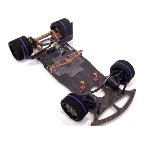
- Page 2 Brushless/LiPo power systems. The result of all of this is the Copperhead 10. This car is everything the DB 10R was and much, much more. All the changes focused on expanding the cars setup envelope.
- Page 3 Special Note: hand thread into the upper arms. The Copperhead 10 uses IRS upper hinge pins Note: and does not require setscrews in the upper The arms have a bottom and a top. They have suspension arm mounts.
- Page 4 Step 7 Step 6 Locate the Ti front axles, four 4-40 alloy lock nuts, and two alloy pivot balls. Thread the Ti axles into the steering spindles. Note that the threads on the axles that go into the spindles are left hand. After the axles are fully seated tighten an alloy 4-40 lock nut onto the threaded stub coming out the back of the spindle.
- Page 5 Tighten both screws. Repeat on the other side. Special Note: You will have to add or subtract spacers in order to achieve your desired ride height. BMI Racing makes alloy spacers you can get a variety of sizes from www.bmiracing.com, (P/N DB5311-DB5316)
-
Page 6: Rear Suspension Assembly
Rear suspension assembly Step 13 Step 14 Locate the delrin center pivot assembly one 4-40 x ¼” and two 4-40 x 3/8” flat head screws. Attach the center pivot assembly to the rear most hole Locate two flex plates*, 2 flex plate pivot assemblies in the center of the lower chassis plate with the ¼”... - Page 7 Step 16 Step 17 Locate and install the two long anodized threaded spacers as shown with 4-40 x ¼” flat head screws Locate the two alloy rear pod plates, the alloy rear pod plate spacer tube 2 4-40 x 3/8” flat head screws and 4 4-40 x ¼”...
- Page 8 Locate the damper tube parts bag, the rear pod top Step 19 plate and 4 4-40 x ¼” flat head screws.. 1.Thread a 4-40 x3/8” set screw into each of the 4 ball cups from the damper parts bag. 2.Thread a ball cup/set screw assembly into the ends of each of the damper tube pistons and damper tubes.
- Page 9 Step 22 Step 23 Locate the rear axle parts bag. There are a couple of steps that can make your diff last longer that should be done at this time. Use the right alloy diff hub as a holder and sand Assemble the IRS Nickel-Teflon Macro Shock as per both sides of each diff ring on 600 grit sand paper using the included instructions with 40wt silicon shock oil.
- Page 10 Shim as necessary to obtain a centered axle and a 200mm rear track width. Special Note: The Copperhead 10 is designed to work with IRS precision ride height adjuster cams. We find too much size variation in other cams and cannot guarantee they will fit properly.
- Page 11 Step 27 The Servo mounts are attached to the lower chassis with two 4-40 x ¼” flat head screws. At this time drill out the center holes on your servo saver (not supplied) for two Nickel Teflon ball studs. Secure them with two 3/16 alloy lock nuts. Locate two titanium turnbuckles and four black ball cups.
- Page 12 Mounting Electronics The “Center Mass“ chassis layout of the Copperhead 10 is one of the features that really puts this car ahead of the pack. This chassis design moves the batteries forward and places the electronics between the battery and the motor pod.
Need help?
Do you have a question about the Copperhead 10 and is the answer not in the manual?
Questions and answers