
Related Manuals for F&S PicoCOM1

Summary of Contents for F&S PicoCOM1
- Page 1 PicoCOM1 Hardware Version 0.70 Date 2012.11.07 © by F & S Elektronik Systeme GmbH 2008 Preliminary F & S Elektronik Systeme GmbH Untere Waldplätze 23 D-70569 Stuttgart Phone: +49-711-123722-0 Fax: +49-711-123722-99...
-
Page 2: Table Of Contents
Table of Contents Arrangement of Connectors ........1 Technical Data Connectors ........2 Connectors ..............3 Counting of the connector pins ........3 IO-Pin limitations ............3 Connector J1 ............... 4 Dimensions PicoCOM1 ..........8 Technical Data PicoCOM1 ........9... -
Page 3: Arrangement Of Connectors
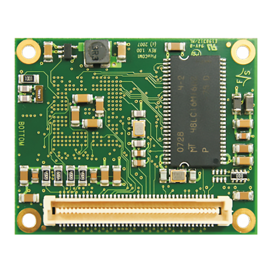
Arrangement of Connectors Figure 1.1: Bottom View Seite 1... -
Page 4: Technical Data Connectors
Technical Data Connectors The PicoCOM1 is equipped with a TycoElectronics 5177984-3 (8 pin, 0.8mm) connector from ‘0.8mm Free Height (FH) Connectors’ series. Matching connectors are: 5mm stacking height: TycoElectronics 5177983-3 9mm stacking height: TycoElectronics 5-5179009-3 13mm stacking height: TycoElectronics 5-5179010-3... -
Page 5: Connectors
1 contains all even-numbered pins (2, 4, 6, 8 etc.). IO-Pin limitations PicoCOM1 is equipped with 43 pins that can be used as digi- tal-IO. Most of these pins are multiplexed, so you have to make sure that these pins are used for one purpose only. For example, if you intend to use IO0 to IO3 you have to make sure that the COM2 is disabled. -
Page 6: Connector J1
Connector J1 Signal Default Interface Starter-Kit Interface Ethernet TX- Ethernet TX- Ethernet RX- Ethernet RX- Ethernet TX+ Ethernet TX+ Ethernet RX+ Ethernet RX+ +3.3V +-5% DC +3.3V +-5% DC +3.3V +-5% DC +3.3V +-5% DC Ground Ground Ground Ground VBAT +3..+3.6V DC (RTC back- +3..+3.6V DC (RTC backup up battery) - Page 7 Signal Default Interface Starter-Kit Interface Ground Ground nTRST JTAG Reset JTAG Reset JTAG TMS JTAG TMS JTAG TDI JTAG TDI JTAG TDO JTAG TDO JTAG TCK JTAG TCK JTAGSEL JTAG Select JTAG Select I2C SDA I2C SCL IO10 IO10 SD DAT0 IO11 IO11 SD DAT1...
- Page 8 Signal Default Interface Starter-Kit Interface CAN+ CAN+ CAN+ CAN- CAN- CAN- HDPB USB Host 2 + USB Host 2 + HDMB USB Host 2 - USB Host 2 - IO26 IO26 SPI MISO IO27 IO27 SPI MOSI IO28 IO28 SPI SPCK IO29 IO29 SPI PCS0...
- Page 9 2) Like 1) theses pins carry internal signals. But this restriction is limited to hardware revisions ≤1.20 only. 3) If using the CAN interface, these pins are restricted to SPI function. See PicoCOM1 starterkit documentation for connection exam- ples. Seite 7...
-
Page 10: Dimensions Picocom1
Dimensions PicoCOM1 Board thickness: 1.6 mm Height of parts on top side: 3.0 mm Height of parts on bottom side (without connectors): 2.0 mm Pin pitch of connector: 0.8 mm Mounting hole diameter 2.8 mm Figure 4.1: Top View Figure 4.2: Bottom View All values can have tolerances of ±0,5mm. -
Page 11: Technical Data Picocom1
Technical Data PicoCOM1 Power Supply: +3.3V DC / ±5% Current Consumption: < 400 mA (<450mA in custom LDO version) <2A on startup up to 2.5V !! we recommend a 2A power source with fast rise time to avoid startup problems !! Inputs/Outputs: max. - Page 12 Index Connectors ................3 Arangement ................1 Connector J1 ................4 Counting ................. 3 Dimensions ................10 Technical Data ................ 11 Note: Changes that serve technical progress are reserved. ARM is a registered trademark of ARM Ltd.
Need help?
Do you have a question about the PicoCOM1 and is the answer not in the manual?
Questions and answers