
Related Manuals for Velleman-Kit K2649

Summary of Contents for Velleman-Kit K2649
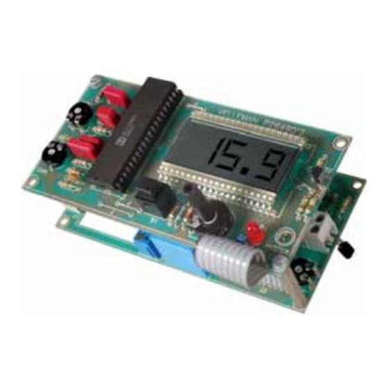
- Page 1 Total solder points: 166 + 116 Difficulty level: beginner 1 advanced THERMOSTAT WITH LCD-DISPLAY K2649 ILLUSTRATED ASSEMBLY MANUAL H2649IP-1...
- Page 3 Features & Specifications The very precise digital display of both the set and actual temperature makes this thermostat very easy to use. Also very useful is the connecting capability for an 'economy switch': when the contact is closed then the set temperature is decreased by a number of degrees.
- Page 4 Assembly hints 1. Assembly (Skipping this can lead to troubles ! ) Ok, so we have your attention. These hints will help you to make this project successful. Read them carefully. 1.1 Make sure you have the right tools: • A good quality soldering iron (25-40W) with a small tip.
- Page 5 Assembly hints 1.3 Soldering Hints : 1- Mount the component against the PCB surface and carefully solder the leads 2- Make sure the solder joints are cone-shaped and shiny 3- Trim excess leads as close as possible to the solder joint AXIAL COMPONENTS ARE TAPED IN THE CORRECT MOUNTING SEQUENCE ! REMOVE THEM FROM THE TAPE ONE AT A TIME !
- Page 6 Construction A. POWER SUPPLY MODE ‘P2649V’ 1. Diode. Watch the polarity ! 4. Resistors 5. Metal film resistors R... R... D5 : 1N4148 D... CATHODE R20 : 10K (1 - 0 - 0 - 2 - 1) (5 - 6 - 1 - B) R21 : 10K (1 - 0 - 0 - 2 - 1) 2.
- Page 7 Construction 7. Ceramic capacitor. 12. Terminal blocks. 10. Capacitor C3 : 100nF (104) C10 : 1µF/63V 8. Transistor. J1 : Mains. J4 : “ES” Economy switch. J2 : T1 : BC557B 11. Vertical trimmer For heaters use the contacts : ‘C’...
- Page 8 Construction 13. Electrolytic Capacitor. 16. Electrolytic Capacitor. 19. Flat cable Watch the polarity ! Watch the polarity ! C1 : 1000µF C2 : 100µF C ... C... J3 : FC8 “9 wire” 14. Fuse holder & Fuse 17. Transformer 220V 20.
- Page 9 Construction B. DISPLAY MODULE ‘P2649D’ 3. Resistors Mount for R13 : 1. Jumpers R... 1M (1-0-5-B) for °C. 150K (1-5-4-B) for °F. For degrees Celsius, the follow- 100K (1 - 0 - 4 - B) J (4x) ing resistors must be fitted too : (1 - 8 - 2 - B) R11 : 120K...
- Page 10 Construction 5. Ceramic capacitors. 8. LCD display C4 : 100nF (104) C6 : 100pF (101) 6. Transistor. T2 : BC557B Attention : For °F this transistor should not be fitted! 7. Horizontal trimmers Fig.1.0 R... RV1 : 4K7 RV2 : 100 First look for pin 1 : if a colon is displayed when connecting the RV3 : 10K battery, then you have the display correctly mounted.
- Page 11 Construction 9. Capacitors Fig. 2.0 C5 : 10nF / 250V Pay attention to the position : the upper surface must be at 8mm C7 : 100nF / 250V C8 : 220nF / 100V (0,3 inch) above the pcb surface (see drawing 2.0). C9 : 470nF / 63V You may put some pieces of paper between the LCD and the pcb, to help you holding the display on the right height.
- Page 12 Construction 11. Push button. 13. Axe. S1 : S500 12. IC. Watch the position of Insert the plastic spindle in trimmer RV1 as displayed. the notch! IC1 : ICL7106...
- Page 13 Sensor 14. Sensor Calibration is performed by alternately adjusting the meter at the freezing respectively boiling-point of water. Therefore the sensor first has to be prepared. DON'T shorten the connection wires of the sensor, unless you are not going to fit it directly onto the pcb in the future.
- Page 14 Sensor Make the connections waterproof with heat-shrinkable tubing : Cut off a piece of shrinking tube with a lenght equal to 5cm. Slide the shrinking tube over the wires and over the sensor (Fig. 4.0). Heat the shrinking tube using a hair dryer or, better still, using a paint stripper. Fig.
- Page 15 Flat cable 15. Flat cable P2649D P2649V Fig. 5.0 Attention : The connecting order (whit regard to the pcb-edge) must be the same as on the power supply module (see fig. 5.0).
- Page 16 Adjustment 16. Adjustment During assembly you already made your choice for degrees Celsius or degrees Fahrenheit version. The adjusting method is the same for both, only the values on the display are different. The figures for Fahrenheit are mentioned within brackets. The first adjustment is done at the freezing-point.
- Page 17 17. Use The set temperature is displayed when you push the button S1. You can change it by gradually turning potentiometer RV1 until the display shows the desired temperature. With the standard values for R2 and R33 (91K resp. 22K), the adjusting range is about 5 to 30°C (40 to 85°F). You can change this range by using other values for R2 and R33 : Range -50°C (-60°F) to 0°C (32°F)
- Page 18 FIG. 7.0 You can lower the set temperature by a number of degrees (preset with RV5), e.g. by night or during your absence, by connecting a switch or a relay contact (e.g. a timer such like K2603 or K1682) at the place marked with 'E.S.' (Economy Switch).
- Page 19 The setting of the hysteresis does not depend on the set temperature. Do not set the minimum hysteresis right from the beginning: in this case the regulation is most precise, however it could happen that the heating gets switched on and off much too fast and too often (e.g. when the thermostat is located near the radiator). This is not too healthy for the heating installation and/or relay, and too much energy is consumed.
-
Page 20: Flat Cable
Mounting 18. Mounting * Spacers & screws are not included. SENSOR FLAT CABLE FIG. 9.0... - Page 21 Mounting The rectangular opening in the power supply module is used as a passage for the wiring to the mains input, the relay output and the E.S. (Economy Switch), see fig. 10 Economy switch Mains FIG. 10 Relay output...
- Page 22 Mounting The display module can be mounted above the power supply module using spacers (See fig. 11). FIG. 11...
- Page 23 Mounting This thermostat exactly fits into the box type B2649. In case you use this box, you can fit the sensor onto the pcb in such a way that it passes through the opening in the side of the bottom. In this way, the sensor reacts more quickly and accurately upon the room temperature, and it doesn't get influenced by the heat-dissipation of the transformer and such-like.
- Page 24 19. PCB layout (Display module)
- Page 25 PCB layout (power module)
- Page 26 Diagram 20. Diagram TRAF01 D1...D4 220VAC LCD1 31/2 DIGIT LCD MODULE A1 ... A4 = IC2 E.S.
- Page 28 VELLEMAN Components NV Legen Heirweg 33 9890 Gavere Belgium Europe www.velleman.be www.velleman-kit.com Modifications and typographical errors reserved © Velleman Components nv. H2649IP - 2004 - ED1 (rev1.0) 5 4 1 0 3 2 9 2 9 1 8 5 3...
Need help?
Do you have a question about the K2649 and is the answer not in the manual?
Questions and answers