Sign In
Upload
Download
Table of Contents
Contents
Add to my manuals
Delete from my manuals
Share
URL of this page:
HTML Link:
Bookmark this page
Add
Manual will be automatically added to "My Manuals"
Print this page
×
Bookmark added
×
Added to my manuals
Manuals
Brands
Adastra Manuals
Amplifier
UA Series
User manual
Adastra UA Series User Manual
Compact 100v mixer-amplifiers
Hide thumbs
1
2
3
4
5
6
7
8
Table Of Contents
9
page
of
9
Go
/
9
Contents
Table of Contents
Troubleshooting
Bookmarks
Table of Contents
Rack Mounting
Front Panel
Rear Panel
Connection and Setup
Speaker Connections
Low Impedance Systems
Operation
Specifications
Troubleshooting
Advertisement
Quick Links
Download this manual
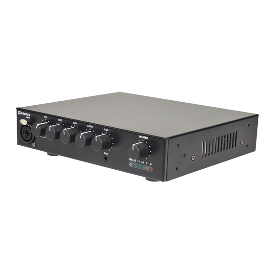
UA-series
Compact 100V mixer-amplifiers
Item ref: UA30 953.183UK
UA60 953.186UK
UA90 953.189UK
User Manual
Version 1.2
Caution: Please read this manual carefully before operating
Damage caused by misuse is not covered by the warranty
Table of
Contents
Previous
Page
Next
Page
1
2
3
4
5
Advertisement
Table of Contents
Need help?
Do you have a question about the UA Series and is the answer not in the manual?
Ask a question
Questions and answers
Related Manuals for Adastra UA Series
Amplifier Adastra UM60 User Manual
Compact 100v mixer-amplifiers (7 pages)
Amplifier Adastra UM Series User Manual
Compact 100v mixer-amplifiers (9 pages)
Amplifier Adastra UM90 User Manual
Compact 100v mixer-amplifiers (9 pages)
Amplifier Adastra UA30 User Manual
Compact 100v mixer-amplifiers (9 pages)
Amplifier Adastra UA60 User Manual
Compact 100v mixer-amplifiers (9 pages)
Amplifier Adastra UA90 User Manual
Compact 100v mixer-amplifiers (9 pages)
Amplifier Adastra US Series User Manual
Compact 100v slave amplifiers (4 pages)
Amplifier Adastra UX Series User Manual
Compact high power 100v mixer-amplifiers (9 pages)
Amplifier Adastra 952.916 Operation Manual
Cd/fm tuner mixer amp (9 pages)
Amplifier Adastra CM30 User Manual
Cm/cs series compact 100v amplifiers (9 pages)
Amplifier Adastra RM60 User Manual
Rm series rackmount 100v mixer-amplifiers item ref: 953.110uk, 953.111uk, 953.112uk (9 pages)
Amplifier Adastra 952.993 Operation Manual
Series 900 240w slave amplifier (8 pages)
Amplifier Adastra 952.996 Operation Manual
900 series 6 channel 120w rms mixer amplifier (8 pages)
Amplifier Adastra PA5120RD Operation Manual
Pa5120 series public address combination mixer amplifiers (12 pages)
Amplifier Adastra RMC120 SERIES User Manual
Rackmount 100v mixer-amplifier with cd player (9 pages)
Amplifier Adastra LA-600 User Manual
Loop amplifier (8 pages)
This manual is also suitable for:
Ua30
Ua60
Ua90
953.183uk
953.186uk
953.189uk
Table of Contents
Print
Rename the bookmark
Delete bookmark?
Delete from my manuals?
Login
Sign In
OR
Sign in with Facebook
Sign in with Google
Upload manual
Upload from disk
Upload from URL


Need help?
Do you have a question about the UA Series and is the answer not in the manual?
Questions and answers