Table of Contents
Advertisement
Quick Links
Swashplate Settings
Enter Setup Mode
Turn on transmitter, press/hold SET, power on
heli, release SET before LEDs stop scrolling.
Setting 1
LED
LED1 Lit
Setting
Mechanical Travel and Neutral point setting
Setup Method
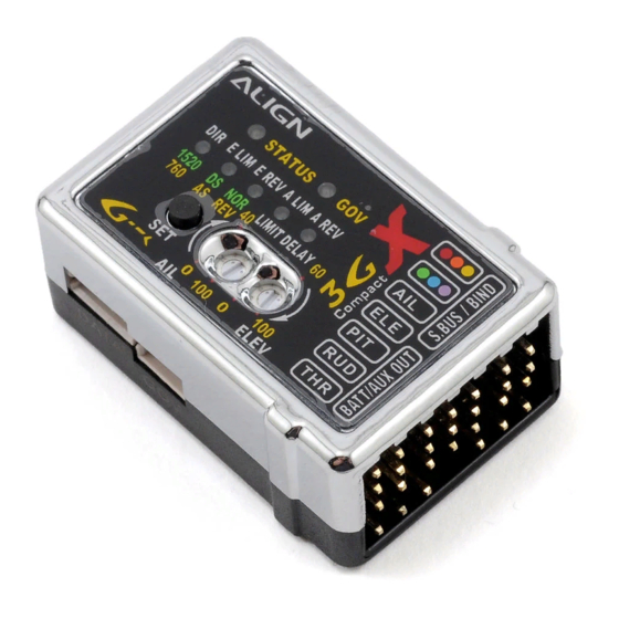
1.Servo on right side of heli frame is AIL, middle is
ELE, left side is PIT. Do not exchange AIL and PIT
connections, otherwise some compensation
feature may be reversed.
2.Confirm proper swashplate action with PIT, AIL,
and ELE commands.
3. If incorrect movements or servo has no
movement, please check servo connection to 3GX
as well as radio control system.
4. Adjust the maximum collective pitch using the
transmitter's swashplate mixing function (pitch
swash AFR). Do not adjust individual servos
endpoints through the servo ATV/AFR function.
Should any changes made to the endpoints or
subtrims on the transmitter in the future, the 3GX
flybarless system initial setup must be performed
again.
3GX V2.1 Easy Setup Table (English).xlsx
Align 3GX V2.1 ‐ Setup Summary
Align 3GX V2.1 ‐ Easy Setup Table
Speed Governor Settings
The 3GX needs to know the maximum and minimum positions of
the throttle and mechanical travel range, you have to set this
function whether you use it or not. Note: Swashplate settings
need to be completed and then set the governor function.
1. Reset throttle curve and pitch curve to default 0‐50‐100.
2. Confirm the transmitter is powered up, and throttle stick is at
lowest position.
3. Press and hold the SET button while powering up the receiver
until all 1~5 LED lights up. Release the SET button and GOV red
LED will light up.
4. Push the throttle stick on transmitter to the maximum top, and
in a few moments LED will go off and system power cycles,
indicating the completion of setup process.
LED1~5 all lit up
Speed governor setup
1. Ensure correct throttle servo direction and mechanical travel
range prior to connecting the governor.
2. Connect wires and install sensor magnet as shown in diagram.
3. When using standard parallel channel layout or S.BUS system to
connect the 3GX, speed setting is done through channel 7.
Turning channel 7 on or off will enable or disable governor
function. When satellite receivers are used, governor speed
setting is done through channel 5.
4. 3GX GOV LED will lit green when governor is active, red when
inactive.
5. 3GX throttle governor has throttle safety built in. If throttle
isn't lowered to minimum during 3GX startup, governor function
will not activate. Restart the 3GX with throttle lowered all the
way down.
6. The following two requirements must be met in order for
governor to activate:
(1) Governor switched on.
(2) Throttle position is at 30% or higher.
D du Rand ‐ July 2012
Rudder Settings
1. Push and hold the SET button for 2 second to enter the
rudder gyro setup mode while 3GX is turned on.
2. Each setting value is labeled on the 3GX control unit with
either green or red lettering, which corresponds to the STATUS
LED color. Subsequent setup mode is entered by a single press
of the SET button. Setup mode will exit if no activity is detected
in 10 seconds.
Wide/narrow servo band setting
1. 3GX Flybarless system is compatible with both the 760μs
narrow frame rate servos (such as Futaba S9256, S9251,
BLS251), as well as the standard 1520μs frame rate servos
(most others). Proper frame rate must be selected based on
your servo's specifications.
2. Push the ransmitter rudder stick left or right to select the
frame rate. For example, if rudder is pushed to the left (or
right) and STATUS LED turns green, the frame rate is set to
1520μs. To set it to 760μs, the rudder stick need to be pushed
from the center to the opposing end 3 times for the STATUS
LED to turn red, indic ating frame rate set to 760μs.
Flight Mode Setting
1.With 3GX in operation mode, push rudder to left or right, and
press the SET button for about a second.
2.After entering setting mode, the STATUS LED will flash specific
number of times to indicate specific settings.
3.During setting process, LED 1 to 5 indicate the rate of setting;
flashing LED represents 10%, while steady lit LED represents 20%.
For example, if LED 1 and LED2 are steady lit with LED3 flashing,
the set rate is 2*20+10=50%.
STATUS flashes green once
Cyclic pitch speed adjustment.
1. After entering setting mode, STATUS LED flashes once.
2. Aileron and elevator rate can be adjusted independently.
3. Moving the aileron stick will display aileron roll rate on the LED.
The more LEDs, the faster the roll rate. Moving the aileron stick
can increase or decrease the number of LEDs that lights up
between LED1 to LED5, which sets the aileron roll rate. Same
method is used to adjust the elevator flip rate when elevator stick
is moved.
4. Elevator flip rate is adjusted based on aileron roll rate. When
the difference between elevator flip rate and aileron roll rate
differs by 20% or more, 3GX will automatically adjust until the
error rate falls within range. Therefore, we recommend
adjustment aileron roll rate first, and then adjust elevator flip rate.
5 .Moving the related control stick, LED will automatically jump to
the set rate display of the specific stick function. For example,
moving the aileron stick, LED1 to LED5 will display aileron set rate.
Moving elevator stick, LED to LED5 will display elevator set rate.
1 of 4
Advertisement
Table of Contents

Subscribe to Our Youtube Channel
Related Manuals for Align 3GX V2.1

Summary of Contents for Align 3GX V2.1
- Page 1 Align 3GX V2.1 ‐ Setup Summary Align 3GX V2.1 ‐ Easy Setup Table Swashplate Settings Speed Governor Settings Rudder Settings Flight Mode Setting Enter Setup Mode Turn on transmitter, press/hold SET, power on The 3GX needs to know the maximum and minimum positions of 1. Push and hold the SET button for 2 second to enter the 1.With 3GX in operation mode, push rudder to left or right, and heli, release SET before LEDs stop scrolling. the throttle and mechanical travel range, you have to set this rudder gyro setup mode while 3GX is turned on. press the SET button for about a second. function whether you use it or not. Note: Swashplate settings need to be completed and then set the governor function. 2. Each setting value is labeled on the 3GX control unit with 2.After entering setting mode, the STATUS LED will flash specific either green or red lettering, which corresponds to the STATUS number of times to indicate specific settings. 1. Reset throttle curve and pitch curve to default 0‐50‐100. LED color. Subsequent setup mode is entered by a single press of the SET button. Setup mode will exit if no activity is detected 3.During setting process, LED 1 to 5 indicate the rate of setting; 2. Confirm the transmitter is powered up, and throttle stick is at in 10 seconds. flashing LED represents 10%, while steady lit LED represents 20%. lowest position. For example, if LED 1 and LED2 are steady lit with LED3 flashing, the set rate is 2*20+10=50%. 3. Press and hold the SET button while powering up the receiver until all 1~5 LED lights up. Release the SET button and GOV red LED will light up. 4. Push the throttle stick on transmitter to the maximum top, and in a few moments LED will go off and system power cycles, indicating the completion of setup process. Setting 1 LED1 Lit LED1~5 all lit up STATUS flashes green once...
- Page 2 Align 3GX V2.1 ‐ Setup Summary Swashplate Settings Speed Governor Settings Rudder Settings Flight Mode Setting 5. Swashplate cyclic pitch setting: with the main 7. When governor is functioning, engine rotational speed is blades parallel to helicopter body, throttle stick controlled by the percentage set by user. The rotation speed of positioned where main pitch is 0 degrees, move main blade is converted according to the engine ratio of original aileron stick all the way to the right, adjust the AIL helicopter. mixing ratio within radio's SWASH menu so the main blade pitch is the factory recommended 8. Using the chart on the right to obtain engine rotation speed and value ±8 degrees. head speed under corresponding governor channel percentage. 6. The ELE mixing ratio in SWASH menu can be set to the same value as AIL. Setting 2 LED2 Lit LED2 Lit STATUS flashes green twice Setting Elevator Travel Limit Setting Digital/Analogue Servo Selection Elevator travel limit setting Setup Method While keeping swashplate level and main pitch at 1. There is a direct correlation between servos' speed to gyro's 1. Before entering elevator and aileron limit setting, please switch zero degrees, press the SET button to register the performance. Faster servos are able to execute commands the transmitter to throttle hold mode and push the throttle down neutral point and enter E.LIM from the gyro at faster and higher precision. Due to the high to 0 degree position to avoid mechanical interference due to setup mode. The E.LIM LED will lit up after DIR performance gyro sensors used in the 3G flybarless system, ...
- Page 3 Align 3GX V2.1 ‐ Setup Summary Swashplate Settings Speed Governor Settings Rudder Settings Flight Mode Setting Setting 4 LED4 LED4 STATUS flashes green 4 times Setting Aileron Travel Limit Setting Rudder Servo Travel Swashplate Dampening Setting Setup Method 1. Press the SET button to enter A.LIM setup 1. Press the SET button to enter LIMIT setup mode. 1. After entering setting mode, STATUS LED flashes 4 times. mode. The A.LIM LED will lit up after E.REV turns off. 2. Push the transmitter rudder stick left until tail pitch slider 2. Move the aileron stick to adjust cyclic pitch dampening rate; the reaches the end, then center the rudder stick and wait 2 more LED lights up, the more dampening effect. Please note 2. With all channels stationary, move the seconds for the STATUS LED to flash red. This completes the aileron and elevator dampening cannot be adjusted separately. transmitter aileron stick to the right, and then rudder endpoint limit adjustment for the left side. Moving aileron stick is for adjusting cyclic pitch dampening rate, back to center position. This completes the but moving elevator stick is for adjusting collective pitch aileron endpoint setup process. The control unit 3. Push the rudder stick right until tail pitch slider reaches dampening rate, NOT elevator dampening rate. will determine the maximum aileron endpoints. the end, then center the rudder stick and wait 2 seconds for the STATUS LED to flash red. This completes the 3. The more dampening effect, the smoother helicopter flies, but rudder endpoint limit adjustment for the right side. feels less direct. The rate of dampening should be adjusted to suit ...
- Page 4 Align 3GX V2.1 ‐ Setup Summary Swashplate Settings Speed Governor Settings Rudder Settings Flight Mode Setting Setting 6 LED 1~5 all lit up Setting Gyro install reverse setting Setup Method 1. To achieve consistent gyro gain on left and right, 3GX has built in anti‐torque compensation function. User need to confirm if 3GX is mounted right side up or upside down. 2. Right side up: Installed with 3GX label facing up, anti‐torque compensation set to positive (green STATUS LED). Upside down: Installed with 3GX label facing down, anti‐torque compensation set to negative(red STATUS LED). 4. Setup method: Press and hold the SET button for 2 seconds to enter setup mode, select until anti‐torque compensation section, as indicated by lighting of all 5 setup mode LEDs. Using the rudder stick to select either positive anti‐torque compensation (green STATUS LED) for right side up mounting, or negative anti‐torque compensation (red STATUS LED)for upside down installation. In addition to transmitter, the anti‐torque compensation feature can also be set through 3GX interface's rudder parameter. Transmitter Setting Rudder Gain Adjustment on Transmitter Setup Method 1. For radio with built in gyro gain settings, gain can be adjusted directly. For example, 50%‐100% setting on the radio translates to 0% ‐ 100% gain in the heading lock mode; 50%‐0% setting on the radio translates to 0%‐100% gain in the normal (non‐heading) lock mode. 2. Actual gain value differs amongst servos and helicopters. The goal is to find the maximum gain without tail hunting. This can only be done through actual flight tests. 3.The recommended starting point for transmitter's gyro gain ...
Need help?
Do you have a question about the 3GX V2.1 and is the answer not in the manual?
Questions and answers