
Related Manuals for Apator Powogaz MWN Nubis


Summary of Contents for Apator Powogaz MWN Nubis
- Page 1 Operating Manual Operating Manual Flanged water meters, DN40-400 IP68/IP65-CE Flanged flow meters, DN40-250 IP68/IP65 JS Impero MWN Nubis MWN/JS- coupled...
-
Page 2: Table Of Contents
Contents 1. Subject ..........................3 2. Technical data: reference standards and regulations ..........7 3. Operating principle of water/flow meters ..............8 4. Selecting the correct size of the water meter .............. 8 5. Selecting the correct size of the irrigation flow meter ..........9 6. -
Page 3: Subject
Thank you for purchasing this product. This Operating Manual applies to the DN 40÷400 flanged water meters and DN 40÷250 irrigation flow meters manufactured by Apator Powogaz S.A. in Poznań according to the manufacturing procedures under the Integrated Environmental, Health and Safety Management System. - Page 4 transmitter • Max operating pressure: 1.6 MPa (16 bar) • Hot water: max. 130°C MWN130 (WPH130-01) – horizontal rotor axis • Max operating pressure: 1.6 MPa (16 bar) propeller • IP65 – hermetic counter, compatible with optical transmitter modules • Hot water: max.
- Page 5 Table 2. Installation orientation Application Water/flow meter type Horizontal Vertical Counter position V, H MWN (WPH-01) Nubis MWN130 (WPH130-01) MWN/JS-S MK-01 MH-01 JS Impero * Maximum installation orientation deviation from the vertical: ±3º Example part designation marking of the MWN (WPH-01) Nubis water meter Type Temperature Nominal diameter...
- Page 6 Example part designation marking of a coupled water meter Master / side water meter type Master water meter size (nominal diameter) / Side water meter Master / side water meter type size (permanent flow rate) Version with the counter compatible with the NK transmitter module MWN/JS –...
-
Page 7: Technical Data: Reference Standards And Regulations
2. Technical data: reference standards and regulations The technical data is specified in the Technical Data Sheets issued for specific water meter types. The water meters meet the following standards and regulations: 1. Directive 2014/32/EU of the European Parliament and of the Council of 26 February 2014 on the harmonisation of the laws of Member States related to the making available on the market of measuring instruments 2. -
Page 8: Operating Principle Of Water/Flow Meters
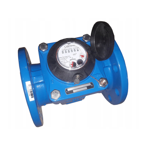
3. Operating principle of water/flow meters The MWN (WPH-01) Nubis water meter comprises a body, metering unit, and counter mechanism. The flow of water passing through the water meter drives the propeller installed in the metering unit. The propeller is co-axial to the body bore and rotates a magnet on an axle via a worm and wheel transmission. -
Page 9: Selecting The Correct Size Of The Irrigation Flow Meter
A water meter that is too small overstresses the mechanism, resulting in premature wear of the moving components. For your water meter to perform properly within its measurement range limits and maximum indication error limits, its operating range must be precisely determined, which can also be achieved based on monthly water demand, considering the minimum and maximum volumetric flow values (for existing installations, it is recommended to monitor the water supply). -
Page 10: Delivery Inspection
Table 4. Maximum permitted loads for irrigation flow meters Type (irrigation flow meter size) Maximum operating flow rate Maximum monthly load limit /month DN (mm) 10,800 12,960 21,600 34,400 54,000 75,600 108,000 194,000 302,000 6. Delivery inspection The measurement device as supplied by the manufacturer requires inspection to verify that no external shipping damage is present, especially on the body, the body flanged ends, the counter guard, and the wiring (if the version includes a transmitter module). -
Page 11: Water Meter Installation Requirements
• Volumetric flow value, Q /h); Measurement unit designation, m (see the counter scale); • • Maximum pressure loss, Δp; For cold water meters: the maximum temperature limit, e.g. T50 (50°C), • • For hot water meters: the maximum temperature limit, e.g. T130 (130°C); Maximum pressure limit: MAP16 (PN 16). -
Page 12: Irrigation Flow Meter Installation Requirements
7.7 Prevent overstressing of the water meter due to the attached piping or other equipment. If necessary, install the water meter on a pedestal or a bracket. The upstream and downstream piping must be properly fastened so that no component of the system shifts by the action of water when the water meter is removed or detached on one of its ends. - Page 13 8.2 Install stop valves upstream and downstream of the irrigation flow meter connections to enable isolation from the water for removal of the irrigation flow meter or its measuring insert for inspection or repairs. 8.3 The piping route geometry at the installation location must prevent air blocks from forming within the installation length of the irrigation flow meter.
-
Page 14: Priming With Water, Commissioning, And Operation Of The Water/Flow Meter
9. Priming with water, commissioning, and operation of the water/flow meter 9.1 Before installing a water/flow meter in the piping, flush the piping to remove all debris and contamination. If a filter is to be used, it must be cleaned before the installation process. For the flushing process, the water/flow meter must be replaced with a straight pipe spool. -
Page 15: Safety And Environmental Requirements
12. Safety and environmental requirements 12.1 The water/flow meter is a measuring instrument which is safe to use, provided it is installed properly and operated according to this Operating Manual. 12.2 Hazards exist during installation, servicing and operation of the product: a) Mechanical hazards (applicable to water/flow meters): Fall during improper handling;... -
Page 16: Pulse Output Value And Installation Diagrams For Water/Flow Meters
13. Pulse output value and installation diagrams for water/flow meters 13.1 Standard water meter version pulse value for the NK transmitter module Cold water Hot water Nominal diameter, DN (mm) Pulse value (m Pulse value (m 0.01 0.01 50; 65; 80; 100; 125 150;... - Page 17 Cable, YTLY 2x0.14 mm , L = 1.5 m * Consult your nearest Apator Powogaz representative for the actual data communication options of WI irrigation flow meters. 13.4 Transmitter cable extension To extend the standard cable of the transmitter module, use a shielded cable with the single core minimum size of 0.75 mm...
-
Page 18: Disposal Of Waste Products And Packaging
View of the counter with an example pulse output View of the counter with the guard and configuration and the IP65 guard assembly removed the IP65 flap shield (for cold water (for cold water operation) operation) NK transmitter, two-wire cable (version NK) NK transmitter, two-wire cable (version NK) green –... - Page 19 Operating Manuals without altering the primary type characteristics. Our Spare Parts Catalogue is available on request. 2021.011.I.EN Apator Powogaz S.A. has the right to modify and improve its products without prior notice. Flanged water meters / flow meters, DN40-400-IP65/68-CE – Operating Manual Page 19 of 19...
Need help?
Do you have a question about the MWN Nubis and is the answer not in the manual?
Questions and answers
why is my meter beeping?