Table of Contents
Advertisement
Quick Links
§ 1-1 Items In Carton
§ 2-1 Best Conditions For Use
When installing and wire connecting on BDE-2007, please follow the guidelines
below:
◎ Before connecting the Electric Power Supply, please identify the input Electric
voltage type is DC 12V or DC 24V.
◎ The Operation Temperature shall range within 0℃ ~ 45℃ , please DO not install in
any place of direct sun-light. Due to the minute output signal from Load Cell,
please use isolated cables. Also, separate the Load Cell cable from the power
supply cable and control I/O cables.
◎The input power shall be DC 12V or DC 24V±10%, if the Electric Power Supply is not stable or the
interference signal exists, that may cause uncertain actuation or reaction, even damage.
Therefore, please utilize Electric Power Supply Stabilizer of adequate capacity.
§ 2-2 Connecting the Load Cell
Do not turn on your power until you have completely connected the load cell.
Screw
1
Positive Excitation Voltage, (EXC+)
2
Positive Sense Voltage, (SEN+)
3
Negative Sense Voltage, (SEN-)
4
Negative Excitation Voltage, (EXC-)
5
Positive Signal Voltage, (SIG+)
6
Negative Signal Voltage, (SIG-)
7
Shield, (SHD)
Indicator use a six-wire cable with shield - connect the wires as indicated above. If
the BDE-2007 / BDE-2007 is located near the Load Cells (Within five meters or a
few yards) you may use a 4-wire cable with shield, but first connect screws 1&2 and
3&4 with independent jumper leads.
The analogue output from the Load Cell and input/output signals are sensitive to
electrical noise. Do not bind these cables together as it could result in cross-talk
interface. Please also keep them away from AC power cables.
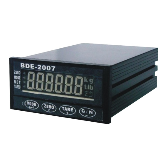
CHAPTER 1 INTRODUCTION
T h e c a r t o n i n w h i c h t h e B D E - 2 0 0 7 i s d e l i v e r e d c o n ta i n s :
1 . I n d i c a t o r.
CHAPTER 2 INSTALLATION
Signal
2 . A c c e s s o r y pa c k ( I n b a g ) .
Open the case, there is a
jumper﹝S1﹞near the
transformer, please insert
a short-circuit pin to the
available side.
To connect your load cell to the weighing
1
3 . M a n u a l .
Advertisement
Table of Contents

Related Manuals for BDE BDE-2007

Summary of Contents for BDE BDE-2007
-
Page 1: Best Conditions For Use
Indicator use a six-wire cable with shield - connect the wires as indicated above. If the BDE-2007 / BDE-2007 is located near the Load Cells (Within five meters or a few yards) you may use a 4-wire cable with shield, but first connect screws 1&2 and 3&4 with independent jumper leads. -
Page 2: Front And Rear Panel Dimensions
§ 2-3 Front and Rear Panel Dimensions Front Panel of BDE-2007 Rear Panel of BDE-2007 Side View of BDE-2007 Mounting Cut for BDE-2007... -
Page 3: Chapter 3 Specifications
0.001% of Dead Comp. Load)/℃ TYP SPAN Temperature ± 0.001% ℃ TYP Comp. Max. Resolution 1/30,000 §3-3 Display and signs * 3-3-1 Front Panel of BDE-2007 Display Spec. 8.8.8.8.8.8 6 digit (Positive) K g ,t,lb Weight indication Status indication ZERO ZERO,M.D.,NET,TARED M.D.(Unstable) -
Page 4: Rear Panel
Press MODE Press Press TARE Press G/N ZERO Mode Tare = Press mode key 1 Manual = Accumulation second. Press mode key 1 ZER0 Tare Clear=Press mode key Gross / Net Change Mode 0 second. >2 second. Tare = Press mode key 1 second. -
Page 5: Chapter 4 System Functions
CHAPTER 4 SYSTEM UNCTIONS § 4-1 System Check A system check should be run: after initial installation, after moving your BDE-2007, after connecting or disconnecting an attachment from the Rear Panel and as means of locating any unexplained system error. - Page 6 F002 Display Update Rate F003 Digital Filter Filter Environment Response 5 Times/Sec Vibration Speed 10 Times/Sec 0 No stage Weak Fast ● 20 Times/Sec stage 40 Times/Sec stage stage F004 Set ZERO Range stage ±5﹪of weighing platform stage...
- Page 7 ◎ Control F102 Timer-Comparator Inhibitor F100 Set ZERO Band Set between 0.0 to 2.0 Sec 6 digit Zero band value (● Initial ”000.000”) (● Initial 0.0 Sec) (Only apply to batching mode 3 and 4). F101 Batching Mode Customer Programmed Control ●...
- Page 8 F203 Output Mode Stream Stable and auto print Manual Print Mode Accumulate and Print For RS-232 commanding For Modbus commanding Serial address (RS-485) F204 F205 RS-232 Models select 00-not used(●Factory set at 00) BDI-2001/ AD4321 00-99 Used BDI-9301 IQ-350 HB-8210 ◎...
-
Page 9: Calibration
§4-3 Calibration ON. Shows CAL → STEP 1: Power OFF, Power ON, Rear Panel SET 1 F-CAL.. ﹝1﹞Setting Minimum Division Press MODE key, displays Use the + or - key to move through the available divisions. ﹝01、02、05﹞. Press the MODE key to set the minimum division. ﹝2﹞Setting Decimal (... -
Page 10: System Initialize
§ 4-4 SYSTEM INITILAIZE STEP 1: Power OFF, slide rear SET 1 STEP 2: Screen shows CAL, Press TARE key until show init STEP 3: Press MODE key, screen will show NO, STEP 4:Press + key to show YES, Press MODE key to confirm → END . STEP 5: Finish initialize, Slide SET and back to normal mode. -
Page 11: Batching Modes
§ 5-2 BATCHING MODES Batching Modes 1. Customer Programmed Control Mode: Normal Batching 2. Customer Programmed Control Mode: Loss-in-Weight Batching 3. Built-in Automatic Program Mode: Normal Batching 4. Built-in Automatic Program Mode: Loss-in weight Batching 5. Multiple-Ingredient Batching ◎ Customer Programmed Control Mode: Normal Batching( F101 = 1) SP1 –... - Page 12 ◎ Customer Programmed Control Mode: Loss-in-Weight ( F101 = 2) SP1 – Supplying Bin Gate SP2 – Full Flow Gate Free – Dribble Flow Gat 1. The Weighing Hopper is empty as is the Receiving Bin. The display shows "0", and all Gates are closed.
- Page 13 Built-in Automatic Program Mode: Normal Batching( F101 = 3 ) SP1 - Full Flow Gate SP2 - Medium Flow Gate Free - Dribble Flow Gate Start signal – Pin22 1. The Weighing Hopper is empty, the display shows "0", and all Gates are closed. If the display is not at ZERO, input a TARE signal (Pin 24) to re-ZERO the display.
- Page 14 ◎ Built-in Automatic Program Mode: Loss-in-Weight Batching (F101=4) SP1 – Supplying Bin Gate SP2 – Full Flow Gate Free – Dribble Flow Gate Start signal – Pin22 1. The Weighing Hopper/ Supply Bin is empty .The display shows "0", and all Gates are closed. 2.
-
Page 15: Chapter 6 Options
TARE Input Clear Tared Weight Pin23 pulse TARE Reset Auto Free Fall When P21 and COM 1 shortage, BDE 2007 will adjust compensation value for next Compen -sation pulse Pin21 batch. And accumulate Net Weight. when batching Clear count and Clear count and accumulation. -
Page 16: Serial Interface
◎ Output When F101=1,2,3,4 Name F101 Description Gross Weight≦ZERO Band Pin13 ZERO Band Batch:Net Weight>=Final-SP1 Pin12 Loss in Weight:Gross Weight>SP1 Net Weight>=Gross-SP2 Pin11 Net Weight>=Final -FF Pin10 Net Weight>Final+Hi value Pin9 Net Weight<Final-Lo Value Pin8 Batch/ Loss-in Weight: Pin7 FINISH Final Output -Finsh Signal F105=0:Stable:Open,Unstable:Short. - Page 17 Built in Automatic Program Control Mode (Only F101=2,3) <HALT BATCHING> R04 Cr Lf Sending Final NET weight. If B Cr Lf is send by BDE-2007, <READS FINAL NET> that means batching is still in process. (Only F101=2,3) Signal “S Cr Lf ” will send back by BDE-2007.
- Page 18 Indicator is busy. ※If an invalid character is received?Cr Lf will be sent by the BDE-2007 ※If the commands are not accepted for any reason:I Cr Lf will be sent by the BDE-2007 ※Batch 1 2 3 4 S Cr Lf Final...
-
Page 19: Analog Output
§ 6-3 Analog OP-05 Please refer to § 4-2 F500 ~ F504 * OP-05 Set at Analog 4 ~ 20mA Range 4 ~ 20mA (Possible: 2 ~ 22mA) Resolution Min. 1 / 3000 Temp. ±(0.015% / ℃of rdg+ coefficient 0.01mA)/ ℃ Max. -
Page 20: Relay Control Interface Op-08
Min. 5KΩ resistance load § 6-4 RELAY CONTROL INTERFACE OP-08 **This option is to connecting BDE 2007 OP-01 Control I/0, which enable OP-01 to RELAY OUTPUT. Specifications: Power: Standard:DC12 from Outside. Pin assignment: Accessory: (1)25PIN Male to Female Wire 1.8 Meter. - Page 21 (A) RELAY TYPE Input (IN) Number of Pins:8. Input Common Pin:COM1 CONTROL I/O Pins OP-08 BDE-2007 Output (OUT): Control I/O Number of Pins:8. PIN 25 Type:for RELAY. PIN 24 Max. Load:250VAC, 30VDC, 3A PIN 23 Output Common Pin:COM2 PIN 22 Input RELAY durance:About 100,000 Times.
-
Page 22: Modbus
§ 6-5 MODBUS Data Register Bit I/O Modbus Type Function Address Description Modbus SCALE address R/W Type Function Address address Output Same as R:02 0000 10001 ZERO 0000 ~ 0001 display Word R:04 30001 ~ 30002 R:02 0001 10002 M.D. Word R:04 0002 ~ 0003 30003 ~ 30004... - Page 24 ※BDE-2007 MODBUS SAMPLE CODE ※Error Code: EX:Read as display:01 04 00 00 00 02 71 CB Function Code Error EX:Read as N.W.:01 04 00 02 00 02 D0 0B Data Address Error EX:Read Final weight:01 03 00 00 00 02 C4 0B Not Valid EX:Read SP1weight:01 03 00 02 00 02 65 CB...
- Page 25 Appendix 2 【Screen characters】...
-
Page 26: Table Of Contents
Contents CHAPTER 1 INTRODUCTION 1-1 Items in Carton --------------------------------------------------------- 1 CHAPTER 2 INSTALLATION 2-1 Best Conditions for Use --------------------------------------------- 1 2-2 Connecting the Load Cell ------------------------------------------- 1 2-3 Front and Rear Panel Dimensions ------------------------------- 2 CHAPTER 3 SPECIFICATIONS 3-1 Analog Input and A/D Conversion --------------------------------- 3 3-2 General ------------------------------------------------------------------ 3-3 Rear Panel -------------------------------------------------------------- CHAPTER 4 SYSTEM FUNCTIONS...
Need help?
Do you have a question about the BDE-2007 and is the answer not in the manual?
Questions and answers