
Subscribe to Our Youtube Channel
Related Manuals for Montana Instruments Cryostation CryoAdvance-50

Summary of Contents for Montana Instruments Cryostation CryoAdvance-50
- Page 1 4400-DOC001 System User Manual Cryostation CryoAdvance-50 | CryoAdvance-100 Version: 1.0 December 2021 www.montanainstruments.com support@montanainstruments.com...
- Page 2 This page intentionally left blank.
- Page 3 Montana Instruments. Montana Instruments, CryoAdvance, Cryostation, CryoOptic, and ATSM are trademarks of Montana Instruments Corporation. Other brand names used are the property of their respective owners.
-
Page 4: Table Of Contents
System User Manual Table of Contents Section 1 - Preface ................................ 7 Conventions Used in this Manual ..........................7 1.1.1 Abbreviations ....................................7 1.1.2 International System of Units (SI) Symbols ........................8 1.1.3 System of Imperial Units Symbols ............................8 1.1.4 Explanation of Safety Warnings ............................. - Page 5 Cryostation Windows ..................................28 3.4.1 Window Covers ..................................28 3.4.2 Window Replacement ................................28 Sample Chamber Wiring ............................. 31 3.5.1 Types of Wiring ..................................31 3.5.2 Thermal Lagging Techniques ............................... 31 3.5.3 User Wiring Interfaces ................................31 3.5.4 Wiring Schematics..................................32 System Care ..................................
- Page 6 System User Manual 5.3.3 Vacuum Check .................................... 53 5.3.4 Helium Check ....................................54 Section 6 - Appendices .............................. 56 Related Documentation ............................. 56 Manual Addendum ........................see Supplement A...
-
Page 7: Section 1 - Preface
All users must read and understand this manual and all other safety instructions before using the equipment. Retain these instructions for future reference. This manual is intended for users of Montana Instruments products and systems described herein. Users include anyone who may physically interact with the system or peripheral equipment, including installation, setup, or configuration . -
Page 8: International System Of Units (Si) Symbols
System User Manual DMM: Digital Multimeter • HDMI: High-Definition Multimedia Interface • Montana Instruments • PCB: Printed Circuit Board • TCM: Temperature Control Module • User Interface • UPS: Uninterruptible Power Supply • USB: Universal Serial Bus • VNC: Virtual Network Computing •... -
Page 9: Graphical Symbols
Cryostation DANGER Serious personal injury Imminent hazards which, if not avoided, will result in serious injury or death. WARNING Serious personal injury Potential hazards which, if not avoided, could result in serious injury or death. CAUTION Possible personal injury Potential hazards which, if not avoided, could result in minor or moderate injury. NOTICE Command or Product Safety Notice Potential hazards which, if not avoided, could result in product damage. -
Page 10: Technical Support Information
Montana Instruments service representative. 1.3.1 Warranty & Repairs If the system or parts need to be returned to the Montana Instruments factory or an authorized service center for repair or service, contact an authorized service representative for a return merchandise authorization (RMA) number and instructions on returning the unit. -
Page 11: Accessories & Replacement Parts
To order spare or replacement parts, please contact your local service representative. • To order new accessories or options, or for more information on other Montana Instruments • products and technologies, please contact your local sales representative. -
Page 12: Section 2 - System Overview
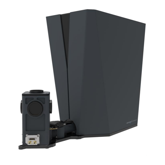
The Cryostation is designed to connect to the system control unit, vacuum control unit, and helium compressor provided by Montana Instruments. The back panel of the Cryostation includes interface locations for these cable and hose connections. -
Page 13: Technical Specifications
Cryostation damping support structure serves to isolate the cryocooler mechanical vibrations from the optical table and sample platform. The cryocooler is part of a closed-loop flow of helium which is pressurized by the separate helium compressor. The cryocooler has two principal stages, each with thermometers to monitor temperature and heaters for warmup. - Page 14 System User Manual Mains Power Connector on Unit IEC 60320 C20 Line Voltage 208 – 240 VAC Frequency 50 – 60 Hz Maximum Current Draw 15 A Maximum Power Consumption 3.12 kW Wall Outlet / N. America & non-EU NEMA 6-20R single-phase (see note below) Receptacle CEE Europe (non-UK) CEE 7/3 or CEE 7/5 w/ common ground terminal...
-
Page 15: Safety Information
Cryostation 2.1.4 Safety Information The following hazards may be typical for this product: WARNING Risk of serious injury due to hazards associated with cryocooling All personnel working with the system must be aware of the potential hazards associated with cryocooling. Personnel working with the system should be trained in emergency measures that may be •... -
Page 16: System Control Unit
Front of Enclosure 2.2.1 Intended Use The system control unit is a device used for instrumentation control of Montana Instruments products. It provides both the electronics hardware and software interface for communicating with other devices and controlling various instrument parameters. - Page 17 Cryostation Enclosure Communication Ports SC1160 (no peripheral cards) rear enclosure SC1160 (two peripheral cards) rear enclosure HDMI The HDMI port on the rear face of the enclosure is used to interface with the touchscreen display. Two USB ports are available on the rear face of the enclosure. One of the USB ports is used to interface with the touchscreen display.
- Page 18 System User Manual Ancillary Control Module (ACM) An ACM peripheral card in the attached system control unit is used to control the valves and pump in the vacuum control unit. The DSUB25 port ( ) on the ACM is VACUUM CONTROL used to interface with the vacuum control unit.
-
Page 19: Technical Specifications
Cryostation 2.2.3 Technical Specifications Environmental Specifications Temperature of Environment 5 – 25 °C Humidity 5 – 80% non-condensing Elevation <2000 m Power Specifications Model SC1160 Mains Power Connector on Unit IEC 60320 C14 Line Voltage 100 – 240 VAC Frequency 50 –... -
Page 20: Vacuum Control Unit
Front of Enclosure 2.3.1 Intended Use The vacuum control unit is used for vacuum control of Montana Instruments Cryostations. It is designed to connect to the system control unit and Cryostation provided by Montana Instruments. It is recommended to locate the vacuum control unit near both connected apparatuses. - Page 21 Cryostation The roughing pump is used to achieve a low vacuum. A high vacuum is achieved with cryopumping. During cooldown, the sample platform temperature lags the Stage 1 temperature in the Cryostation by ~100 K this allows for remaining molecules to be trapped by the charcoal adsorbers and cold surfaces conductively connected to Stage 1 rather than the sample.
-
Page 22: Technical Specifications
System User Manual 2.3.3 Technical Specifications Environmental Specifications Temperature of Environment 5 – 25 °C Humidity 5 – 80% non-condensing Elevation <2000 m Power Specifications Model VC1110, VC1130 Mains Power Connector on Unit IEC 60320 C14 Line Voltage 100 – 240 VAC Frequency 50 –... - Page 23 Cryostation WARNING High voltage: danger of electric shock Electric shocks and burns from capacitor discharge or power circuits could lead to serious injury or death. Completely power down the system and unplug the power cable before accessing the enclosure • or when otherwise servicing the unit (authorized service personnel only),.
-
Page 24: Section 3 - Sample Chamber Configuration
System User Manual Section 3 - Sample Chamber Configuration 3.1 Accessing the Sample Space Before starting the Cryostation, check the sample space. Depending on the configuration, there may be foam inserts to remove before cooling the system down for the first time. Check the Manual Addendum for instructions specific to your configuration. -
Page 25: Sample Mounting
Cryostation 3. Lift the cap from the radiation shield to remove it. 4. Unfasten the 4x M3 button head screws on each side of the radiation shield; lift up and over any sample mount structures to remove. Step 4: Removing screws Step 4: Lifting off radiation shield assembly NOTICE Take care when reassembling the sample chamber... -
Page 26: Mounting A Thermometer
System User Manual Attach sample mount to exchange boss Step 1: Clean the surface of the mounting platform Step 2: Grease mounting surface Step 3: Attaching new sample » NOTE To check if the sample is secure, hold the sample mount horizontally so the sample faces down and forcibly tap the mount with a finger. - Page 27 Cryostation 2. Clean off the area where the thermometer will be mounted with isopropyl alcohol or acetone. 3. Attach the thermometer, ensuring the bottom is in even, flat contact with the mounting surface. a. With Clamp: Apply a thin layer of N-grease to the bottom of the thermometer. Clamp it down securely, ensuring no part of the thermometer “springs up”...
-
Page 28: Windows
System User Manual 3.4 Windows 3.4.1 Window Covers The standard sample chamber has five optical access locations. The system ships with window covers in place. The window covers are removed by turning counter-clockwise until the notches are aligned with the openings in the window retaining ring. To replace the covers, re-align the notches and turn clockwise until the cover locks in place. - Page 29 Cryostation Steps 1-2: Using window tool to unscrew the retaining Step 3: Removing the retaining ring ring Window centered on O-ring NOTICE Take care when handling and removing windows Handle the radiation shield and windows carefully to prevent scratches or fingerprints. •...
- Page 30 System User Manual Radiation Shield Windows The inner (cold) windows on the radiation shield are held in place with a tension ring. 1. Depending on the model, the radiation window holders are removed by unscrewing the threaded tension ring or removing the four M2 screws surrounding the window. 2.
-
Page 31: Sample Chamber Wiring
Cryostation 3.5 Sample Chamber Wiring 3.5.1 Types of Wiring Various applications require different types of wiring. Always select the optimal wire for the application with the appropriate diameter (between 32-40 gauge). Longer wires are ideal -- the length of wiring between stages should be at least 2 in (5 cm). -
Page 32: Wiring Schematics
System User Manual NOTICE Do NOT remove sample chamber circuit boards The standard 4 K circuit board “wedge” (contains USER, SAMPLE THERM, etc.) used on • CryoAdvance-100 models should not be removed as it can lead to the disconnecting of the platform thermostat and heater. - Page 33 Cryostation CryoAdvance-50 All wiring must be routed from the sample chamber circuit board under the thermal clamps into the cold space. CryoAdvance-50 PCB diagram...
- Page 34 System User Manual User 30K Platform 30K Platform Internal Connections External External Interface Internal Internal Temperature Pins DC1, PIN 1 DC1, PIN 1 DC2, PIN 1 DC2, PIN 1 Channel PIN 1 DC1, PIN 2 DC1, PIN 2 DC2, PIN 2 DC2, PIN 2 PIN 2 DC1, PIN 3...
- Page 35 Cryostation CryoAdvance-100 Cryostation CA-100 user wiring to the 4 K circuit board shown below is “pre-lagged” and does not need to be routed under the thermal clamps. Other inputs will require proper thermal lagging. Internal Sample Chamber PCB @ 4 K External DC Connector ‘USER’...
-
Page 36: System Care
System User Manual 3.6 System Care Recommend system care procedures should be followed by any users of the system. For further information on any of these procedures, contact an authorized service representative for assistance. 3.6.1 When Working in the Sample Chamber Keep surfaces clean. -
Page 37: Long-Term Maintenance
Cryostation 1. Clean off old VGE with acetone or isopropyl alcohol then add a thin layer of VGE in the same location. Discard and replace VGE annually - VGE has a limited shelf life of one year. • Check cryocooler/compressor hours to see if maintenance is needed. •... - Page 38 System User Manual adsorber must be replaced after extended operation. This maintenance procedure can be completed at the same time as cryocooler 20,000-hour maintenance.
-
Page 39: Section 4 - System Usage & Operation
Cryostation Section 4 - System Usage & Operation 4.1 System Control Options 4.1.1 User Interface The touchscreen display provides the primary user interface control of the system. General Navigation The example screen above shows the general layout, navigation, and controls for the UI. Not all controls and views will be available for all instruments. - Page 40 System User Manual c. Input Settings: Buttons with numerical values and units show the current input settings for a given command. To set new values, use the adjustment controls (if available) or press the display box to open an input popup dialog. 3.
-
Page 41: Network Interface
Cryostation 4.1.2 Network Interface To utilize any of the provided network services, the system control unit must be connected to a local network using the Ethernet port on the rear face of the enclosure. Each service uses a different network port number for communication. You may need to work with your IT department to configure these ports to be allowed through the firewall on your network. -
Page 42: Primary Operations
MI Remote Support Secure SSH tunnel port 2223 The Montana Instruments Remote Support connection is used by authorized service representatives to remotely access your system to provide diagnostic and troubleshooting support. If the system is behind a NAT/Firewall, the firewall must allow the system to connect a Secure SSH tunnel on port 2223 to mirs.montanainstruments.com. -
Page 43: Controlling System Temperature
Cryostation The software will initialize and run automatically. The UI will indicate the software is INITIALIZING while the system checks for and establishes a connection with the attached peripheral cards. After the screen shows the system is ready for operation. READY 4.2.2 Controlling System Temperature temperature channel is used to drive control operations across the Cryostation,... -
Page 44: Venting And Pulling Vacuum
System User Manual Warming Up the System A warmup operation is used to bring the system to room temperature to access the sample chamber. The system may be warmed up actively with heaters at any time, including during a cooldown. 1. -
Page 45: Moving The System
4.3 Moving the System If the system ever needs to be moved to a different lab or location, follow the steps below or reach out to the Montana Instruments Service team for guidance: 1. Save any important data on the system. -
Page 46: Section 5 - Diagnostics & Troubleshooting
System User Manual Section 5 - Diagnostics & Troubleshooting This section contains information for basic system diagnostics and troubleshooting advice. Diagnostics or repairs outside of the scope of this section should be completed by an authorized service representative. 5.1 Expected System Performance Each system ships with a unique Certificate of Performance to demonstrate the factory performance of that Cryostation. -
Page 47: Power And Communication Issues
Cryostation 5.2.2 Power and Communication Issues If the system will not turn on, run commands, or display readouts, check for these common issues: Problem/Symptom Possible Cause Solution/Suggestion The system throws an Wall power issue 1. Check the wall voltage using an AC electrical breaker voltmeter (digital multi-meter on the AC setting) to ensure it is in the defined... -
Page 48: Compressor Issues & Fault Messages
System User Manual Communication issue with 1. Make sure all cables and power cords are vacuum control unit connected properly. See Connecting System Cables and Power section of the Installation Procedure for details. 2. Ensure the power switch on the back of Vacuum pressure reading the vacuum control unit is ON ( | ). - Page 49 Cryostation Problem/Symptom Possible Cause Solution/Suggestion UI indicates “Cryocooler Power dropped out with compressor or Check cable power Disconnected” communication lost connections. See Power and Communication Issues section. Check the in the UI Compressor display screen EVENT LOG for any fault messages. blank MENU Display screen failure...
-
Page 50: System Checks
System User Manual Low Oil Flow Occurs when the oil flow ratio falls Check that the supply and below 0.4. This alarm indicates that the return lines are properly flow of oil through the oil cooling coil is attached, and there is nothing insufficient. -
Page 51: Temperature Optimization
Cryostation 5.3.1 Temperature Optimization Cryostation platforms are optimized to control heat loads reaching the sample. To ensure the lowest possible base temperatures, follow the best practices below. 1. Use proper thermal lagging techniques for any wiring (including coax) entering the sample space. - Page 52 System User Manual The base temperature for a standard CryoAdvance-50 under normal operating conditions is depicted below. The gradient between the platform and sample will change depending on the type of sample mount and other options. Stage 1 Stage 2 Platform Sample Temperature...
-
Page 53: Vibration Mitigation
Cryostation 5.3.2 Vibration Mitigation The Cryostation and sample chamber have several vibration-damping design features to reduce the effects of cryocooler mechanical vibrations on the sample platform. To ensure the lowest possible mechanical vibrations, follow the best practices below. 1. Rigidly bolt the system to the optical table using all available mounting locations in the baseplate. -
Page 54: Helium Check
System User Manual 3. Check the O-rings on 1) the sample chamber vacuum housing 2) the vacuum housing lid and 3) the vacuum housing outer “warm” windows. Ensure the O-rings have a thin layer of L-grease and are completely free of debris or fibers. a. - Page 55 Contact an authorized service representative for instructions on this process, or find the service document “CryoAdvance B-01 Compressor Recharge Procedure” on the appropriate product page on the Montana Instruments website. NOTICE Follow instructions carefully To avoid possible contamination, these instructions must be followed carefully.
-
Page 56: Section 6 - Appendices
System User Manual Section 6 - Appendices 6.1 Related Documentation For a copy of associated documentation, see below: Document Title Location CryoAdvance-50 https://www.montanainstruments.com/products/ca50r1 Documentation CryoAdvance-100 https://www.montanainstruments.com/products/ca100r1 Documentation General Terms and Direct Link to latest PDF Conditions of Sale Or find the link at the bottom of our homepage Limited Warranty https://www.montanainstruments.com/support/warranty-information...
Need help?
Do you have a question about the Cryostation CryoAdvance-50 and is the answer not in the manual?
Questions and answers