
Related Manuals for ASROCK B550D4ID-2L2T


Summary of Contents for ASROCK B550D4ID-2L2T
- Page 1 B550D4ID-2L2T User Manual Version 1.0 Published June 2021 Copyright©2021 ASRock Rack INC. All rights reserved.
- Page 2 (including damages for loss of profits, loss of business, loss of data, interruption of business and the like), even if ASRock Rack has been advised of the possibility of such damages arising from any defect or error in the documentation or product.
- Page 3 Contact Information If you need to contact ASRock Rack or want to know more about ASRock Rack, you’re welcome to visit ASRock Rack’s website at www.ASRockRack.com; or you may contact your dealer for further information. ASRock Rack Incorporation 6F., No.37, Sec. 2, Jhongyang S. Rd., Beitou District, Taipei City 112, Taiwan (R.O.C.)
-
Page 4: Table Of Contents
Contents Chapter 1 Introduction Package Contents Specifications Unique Features Motherboard Layout Onboard LED Indicators I/O Panel Block Diagram Chapter 2 Installation Screw Holes Pre-installation Precautions Installing the CPU Installing the CPU Fan and Heatsink Installing Memory Modules (DIMM) Expansion Slot (PCI Express Slot) Onboard Headers and Connectors ATX PSU / DC-IN Power Connections Unit Identification purpose LED/Switch... - Page 5 3.1.2 Navigation Keys Main Screen Advanced Screen 3.3.1 CPU Configuration 3.3.2 Chipset Configuration 3.3.3 Storage Configuration 3.3.4 ACPI Configuration 3.3.5 USB Configuration 3.3.6 Super IO Configuration 3.3.7 Serial Port Console Redirection 3.3.8 H/W Monitor 3.3.9 RAM Disk Configuration 3.3.10 Tls Auth Configuration 3.3.11 AMD PBS 3.3.12 AMD Overclocking 3.3.13 AMD CBS...
- Page 6 3.6.1 CSM Parameters Exit Screen Chapter 4 Software Support Install Operating System Support CD Information 4.2.1 Running The Support CD 4.2.2 Drivers Menu 4.2.3 Utilities Menu 4.2.4 Contact Information Chapter 5 Troubleshooting Troubleshooting Procedures Technical Support Procedures Returning Merchandise for Service...
-
Page 7: Chapter 1 Introduction
In case any modifications of this manual occur, the updated version will be available on ASRock Rack website without further notice. You may find the latest memory and CPU support lists on ASRock Rack website as well. ASRock Rack’s Website: www.ASRockRack.com If you require technical support related to this motherboard, please visit our website for specific information about the model you are using. -
Page 8: Specifications
1.2 Specifications B550D4ID-2L2T MB Physical Status Form Factor Deep mini-ITX Dimension 6.7'' x 8.2'' (17.0 cm x 20.8 cm) Processor System AMD Ryzen™ 5000 Series Desktop Processors AMD Ryzen™ 4000 G-Series Desktop Processors with Radeon™ Graphics AMD Ryzen™ PRO 4000 and 3000 Series Desktop Processors Gen AMD Ryzen™... - Page 9 B550D4ID-2L2T LAN Controller - 2 x RJ45 10G base-T by Intel® X710-AT2 - 2 x RJ45 1G RJ45 by Intel® i210 - 1 x RJ45 Dedicated IPMI LAN port by RTL8211E - Supports Wake-On-LAN - Supports Energy Efficient Ethernet 802.3az...
- Page 10 32MB AMI UEFI Legal BIOS BIOS Features - Plug and Play (PnP) - ACPI 2.0 Compliance Wake Up Events - SMBIOS 2.8 Support - ASRock Rack Instant Flash Hardware Monitor Temperature - CPU/DDR/FCH Temperature Sensing - MB/Card Side Temperature Sensing...
-
Page 11: Unique Features
POST or the <F2> key to enter into the BIOS setup menu to access ASRock Rack Instant Flash. Just launch this tool and save the new BIOS file to your USB flash drive, floppy disk or hard drive, then you can update your BIOS only in a few clicks without preparing an additional floppy diskette or other complicated flash utility. -
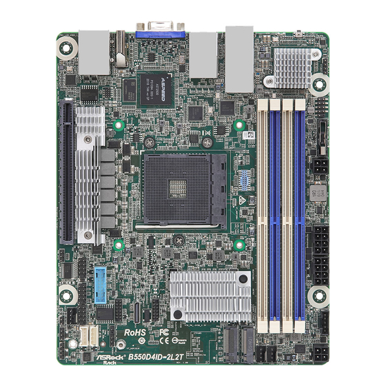
Page 12: Motherboard Layout
1.4 Motherboard Layout 20.8cm (8.2 in) SATA_PWR1 LED_LAN_3_4 (FOR HDD POWER) PSU_SMB1 NCSI1 BAT1 ATX4PIN1 ATX12V1 ATX12V2 UID1 DDR4_B2 DDR4_B1 UID_LED1 FAN1 DDR4_A2 DDR4_A1 FAN2 M2_1 TPM1 CLRCMOS1 VGA1 ASPEED AST2500 OCU1 NUT80_1 TPM_BIOS_PH1 HDMI1 USB3_5_6 IPMB1 COM1 ITX_AUX_PANEL1 FAN3 BMC_SMB1 NUT110_1 PCIE7... - Page 13 B550D4ID-2L2T Description Front LAN LED Connector (LED_LAN_3_4) NCSI Header (NCSI1) SATA Power Connector (DC-IN Mode) (SATA_PWR1)** ATX 12V Power Connector (ATX12V1) ATX 12V Power Connector (ATX12V2) PSU SMBus Header (PSU_SMB1) ATX 12V Power Connector (ATX4PIN1)** System Fan Connector (4-pin) (FAN1) System Fan Connector (4-pin) (FAN2) M.2 Socket (M2_1) (Type 2280)
-
Page 14: Onboard Led Indicators
1.5 Onboard LED Indicators... - Page 15 B550D4ID-2L2T Item Status Description SB_PWR1 Green STB PWR ready FAN_LED1 Amber FAN1 failed FAN_LED2 Amber FAN2 failed FAN_LED3 Amber FAN3 failed SYS_FAULT_LED1 Amber System Fault LED BMC_LED1 Green BMC heartbeat LED...
-
Page 16: I/O Panel
1.6 I/O Panel No. Description No. Description UID Switch (UID1) 1G LAN RJ-45 Port (LAN4)*** UID LED (UID_LED1) VGA Port (VGA1) 10G LAN RJ-45 Port (LAN1)** HDMI Port (HDMI1) 10G LAN RJ-45 Port (LAN2)** USB 3.2 Gen1 Ports (USB3_1_2) 1G LAN RJ-45 Port (LAN3)*** LAN RJ-45 Port (IPMI_LAN1)* *There are two LED next to the LAN port. - Page 17 B550D4ID-2L2T **There are two LEDs on each LAN port. Please refer to the table below for the LAN port LED indications. SPEED LED ACT/LIN K LED SPEED LED ACT/LIN K LED LAN Port 10G LAN Port (LAN1, LAN2) LED Indications...
-
Page 18: Block Diagram
1.7 Block Diagram B550D4ID-2L2T M2_1 DDR4 UDIMM 3200MT/s AMD PROCESSOR PCIE7 Socket AM4 (PGA 1331) Support Max:105 W 2xUSB 3.2 2xUSB 3.2 Intel X710-AT2 USB 2.0 PCIe GEN2 x1 Fusion Control Hub AST2500 B550 D-SUB Intel PCIE x1 i210 Intel... -
Page 19: Chapter 2 Installation
B550D4ID-2L2T Chapter 2 Installation This is a deep mini-ITX form factor (6.7’’ x 8.2’’, 17.0 cm x 20.8 cm) motherboard. Before you install the motherboard, study the configuration of your chassis to ensure that the motherboard fits into it. Make sure to unplug the power cord before installing or removing the motherboard. Failure to do so may cause physical injuries to you and damages to motherboard components. -
Page 20: Installing The Cpu
2.3 Installing the CPU Unplug all power cables before installing the CPU. -
Page 21: Installing The Cpu Fan And Heatsink
B550D4ID-2L2T 2.4 Installing the CPU Fan and Heatsink Please be aware that this motherboard only supports LGA115x CPU heatsink... -
Page 22: Installing Memory Modules (Dimm)
2.5 Installing Memory Modules (DIMM) This motherboard provides four 288-pin DDR4 (Double Data Rate 4) DIMM slots, and supports Dual Channel Memory Technology. 1. For dual channel configuration, you always need to install identical (the same brand, speed, size and chip-type) DDR4 DIMM pairs. 2. - Page 23 B550D4ID-2L2T The DIMM only fits in one correct orientation. It will cause permanent damage to the motherboard and the DIMM if you force the DIMM into the slot at incorrect orientation.
-
Page 24: Expansion Slot (Pci Express Slot)
2.6 Expansion Slot (PCI Express Slot) There is 1 PCI Express slot on this motherboard. PCIE slot: PCIE7 (PCIE 4.0 x16 slot, from CPU) is used for PCI Express x16 lane width cards. Slot Generation Mechanical Electrical Source PCIE7 Installing an expansion card Step 1. -
Page 25: Onboard Headers And Connectors
B550D4ID-2L2T 2.7 Onboard Headers and Connectors Onboard headers and connectors are NOT jumpers. Do NOT place jumper caps over these headers and connectors. Placing jumper caps over the headers and connectors will cause permanent damage to the motherboard. LAN1_ACT# Auxiliary Panel Header... - Page 26 System Fan Connectors Please connect fan cables to the FAN_SPEED (4-pin FAN1) fan connector and match the FAN_VOLTAGE_CONTROL FAN_SPEED_CONTROL (see p.6, No. 8) black wire to the ground pin. (4-pin FAN2) All fans support Fan Control. (see p.6, No. 9) (4-pin FAN3) (see p.6, No.
- Page 27 B550D4ID-2L2T SPI TPM Header This connector supports SPI SPI_DQ3 +3.3V (13-pin TPM_BIOS_PH1) Trusted Platform Module TPM_Present (see p.6, No. 14) SPI_MOSI (TPM) system, which can RST# securely store keys, digital TPM_PIRQ certificates, passwords, and data. A TPM system also helps...
- Page 28 NCSI Header The onboard NCSI header is (9-pin NCSI1) used for external connections. (see p.6, No. 2) PWM Configuration This header is used for PWM Header configurations. (3-pin PWM_CFG1) (see p.6, No. 23) ATX 12V Power The motherboard provides two Connectors 8-pin 12V power connectors (8-pin ATX12V1)
- Page 29 B550D4ID-2L2T ATX 4-PIN Power The motherboard provides one Connector 4-pin power/signal connector ATX_PG (4-pin ATX4PIN1) which is a required input for +5VSB PSON# (see p.6, No. 7) ATX power source. When using ATX power, it is necessary to use a 24pin-to-...
-
Page 30: Atx Psu / Dc-In Power Connections
2.8 ATX PSU / DC-IN Power Connections This motherboard supports both +12V DC and ATX power input. Please refer to the table below for the required connections between the motherboard and the power supply. Connector DC-IN ATX PSU 12V 8pin ATX 4pin (with the bundled ATX 24pin-to-4pin converter cable) -
Page 31: Unit Identification Purpose Led/Switch
B550D4ID-2L2T 2.9 Unit Identification purpose LED/Switch With the UID button, You are able to locate the server you’re working on from behind a rack of servers. Unit Identification When the UID button on the purpose LED (UID_ front or rear panel is pressed,... - Page 32 2.11 M.2_SSD (NGFF) Module Installation Guide (M2_1) The M.2, also known as the Next Generation Form Factor (NGFF), is a small size and versatile card edge connector that aims to replace mPCIe and mSATA. The M.2 Socket (M2_1) supports a M.2 SATA3 6.0 Gb/s module or a M.2 PCI Express module up to Gen4 x4 (64Gb/s).
-
Page 33: Chapter 3 Uefi Setup Utility
B550D4ID-2L2T Chapter 3 UEFI Setup Utility 3.1 Introduction This section explains how to use the UEFI SETUP UTILITY to configure your system. The UEFI chip on the motherboard stores the UEFI SETUP UTILITY. You may run the UEFI SETUP UTILITY when you start up the computer. Please press <F2> or <Del> during the Power-On-Self-Test (POST) to enter the UEFI SETUP UTILITY;... -
Page 34: Navigation Keys
3.1.2 Navigation Keys Please check the following table for the function description of each navigation key. Navigation Key(s) Function Description Moves cursor left or right to select Screens Moves cursor up or down to select items + / - To change option for the selected items <Tab>... -
Page 35: Main Screen
B550D4ID-2L2T 3.2 Main Screen Once you enter the UEFI SETUP UTILITY, the Main screen will appear and display the system overview. The Main screen provides system overview information and allows you to set the system time and date. -
Page 36: Advanced Screen
3.3 Advanced Screen In this section, you may set the configurations for the following items: CPU Configura- tion, Chipset Configuration, Storage Configuration, ACPI Configuration, USB Configura- tion, Super IO Configuration, Serial Port Console Redirection, H/W Monitor, RAM Disk Configuration, Tls Auth Configuration, AMD PBS, AMD Overclocking, AMD CBS and Instant Flash. -
Page 37: Cpu Configuration
B550D4ID-2L2T 3.3.1 CPU Configuration PSS Support Enable/disable the generation of ACPI _PPC, _PSS, and _PCT objects. SPI/LPC/fTPM TPM switch To select. 0: AMD CPU fTPM. 1 - LPC TPM. 2 - SPI TPM SVM Mode Enable/disable CPU Virtualization. -
Page 38: Chipset Configuration
3.3.2 Chipset Configuration Above 4G Decoding Globally Enables or Disables 64bit capable Devices to be Decoded in Above 4G Address Space (Only if System Supports 64 bit PCI Decoding). SR-IOV Support If system has SR-IOV capable PCIe Devices, this option Enables or Disables Single Root IO Virtualization Support. -
Page 39: Storage Configuration
B550D4ID-2L2T 3.3.3 Storage Configuration SATA Mode Select SATA Mode. Storage Configuration of Vermeer / Matisse series CPU Configure storage devices of Vermeer / Matisse series CPU. -
Page 40: Acpi Configuration
3.3.4 ACPI Configuration PCIE Devices Power On Allow the system to be waked up by a PCIE device and enable wake on LAN. RTC Alarm Power On Allow the system to be waked up by the real time clock alarm. Set it to By OS to let it be handled by your operating system. -
Page 41: Usb Configuration
B550D4ID-2L2T 3.3.5 USB Configuration Legacy USB Support Enables Legacy USB support. AUTO option disables legacy support if no USB devices are connected. DISABLE option will keep USB devices available only for EFI applications. -
Page 42: Super Io Configuration
3.3.6 Super IO Configuration Serial Port 1 Configuration Use this item to set parameters of Serial Port 1 (COM1). Serial Port Use this item to enable or disable the serial port. Serial Port Address Use this item to select an optimal setting for Super IO device. SOL Configuration Use this item to set parameters of SOL. -
Page 43: Serial Port Console Redirection
B550D4ID-2L2T 3.3.7 Serial Port Console Redirection COM1 / SOL Console Redirection Use this option to enable or disable Console Redirection. If this item is set to Enabled, you can select a COM Port to be used for Console Redirection. Console Redirection Settings Use this option to configure Console Redirection Settings, and specify how your computer and the host computer to which you are connected exchange information. - Page 44 Bits Per Second Use this item to select the serial port transmission speed. The speed used in the host computer and the client computer must be the same. Long or noisy lines may require lower transmission speed. The options include [9600], [19200], [38400], [57600] and [115200]. Data Bits Use this item to set the data transmission size.
- Page 45 B550D4ID-2L2T Redirect After POST When Bootloader is selected, then Legacy Console Redirection is disabled before booting to legacy OS. When Always Enable is selected, then Legacy Console Redirection is enabled for legacy OS. Default setting for this option is set to Always Enable.
-
Page 46: H/W Monitor
3.3.8 H/W Monitor In this section, it allows you to monitor the status of the hardware on your system, includ- ing the parameters of the CPU temperature, motherboard temperature, CPU fan speed, chassis fan speed, and the critical voltage. Watch Dog Timer This allows you to enable or disable the Watch Dog Timer. -
Page 47: Ram Disk Configuration
B550D4ID-2L2T 3.3.9 RAM Disk Configuration Disk Memery Type Specifies type of memory to use from available memory pool in system to create a disk. Create raw Create a raw RAM disk. Create from file Create a RAM disk from a given file. -
Page 48: Tls Auth Configuration
3.3.10 Tls Auth Configuration Server CA Configuration Press <Enter> to configure Server CA. Client Cert Configuration Enroll Cert Press <Enter> to enroll cert. Delete Cert Press <Enter> to delete cert. -
Page 49: Amd Pbs
B550D4ID-2L2T 3.3.11 AMD PBS AMD Firmware Version Show all of AMD Firmware Version. Gaphics Features Graphics Features - HG, DGPU Features, BOMAC0. MITT/WITT Selection Use this item to configure MITT/WITT Selection. LAN Power Enable Use this item to enable or disable LAN power. - Page 50 PM L1 SS Enable for PM L1 SS and ASPM L1 SS. Data Link Feature Exchange Enable or Disable Data Link Feature Exchange, try to disable it if any Legacy Endpoint can not boot. Unused GPP Clocks Off Turn Unused GPP Clocks Off. Clock Power Management (CLKREQ#) Enable or disable CLKREQ#.
- Page 51 B550D4ID-2L2T Thunderbolt Support Enable Thunderbolt Support. Zero-Power ODD Enable/Disable Zero-Power ODD Feature.
-
Page 52: Amd Overclocking
3.3.12 AMD Overclocking The AMD Overclocking menu accesses options for configuring CPU frequency and voltage. -
Page 53: Amd Cbs
B550D4ID-2L2T 3.3.13 AMD CBS CPU Common Options Use this item to configure CPU Common options. DF Common Options Use this item to configure DF Common options. UMC Common Options Use this item to configure UMC Common options. NBIO Common Options Use this item to configure NBIO Common options. -
Page 54: Instant Flash
3.3.14 Instant Flash Instant Flash is a UEFI flash utility embedded in Flash ROM. This convenient UEFI update tool allows you to update system UEFI without entering operating systems ® first like MS-DOS or Windows . Just save the new UEFI file to your USB flash drive, floppy disk or hard drive and launch this tool, then you can update your UEFI only in a few clicks without preparing an additional floppy diskette or other compli- cated flash utility. -
Page 55: Server Mgmt
B550D4ID-2L2T 3.4 Server Mgmt Wait For BMC Wait For BMC response for specified time out. BMC starts at the same time when BIOS starts during AC power ON. It takes around 90 seconds to initialize Host to BMC interfaces. -
Page 56: System Event Log
3.4.1 System Event Log SEL Components Change this to enable ro disable event logging for error/progress codes during boot. Erase SEL Use this to choose options for earsing SEL. When SEL is Full Use this to choose options for reactions to a full SEL. Log EFI Status Codes Use this item to disable the logging of EFI Status Codes or log only error code or only progress code or both. -
Page 57: Bmc Network Configuration
B550D4ID-2L2T 3.4.2 BMC Network Configuration BMC Out of Band Access Enabled/Disabled BMC Out of band Access. Lan channel (Failover) Manual Setting IPMI LAN If [No] is selected, the IP address is assigned by DHCP. If you prefer using a static IP address, toggle to [Yes], and the changes take effect after the system reboots. - Page 58 The default login information for the IPMI web interface is: Username: admin Password: admin For more instructions on how to set up remote control environment and use the IPMI man- agement platform, please refer to the IPMI Configuration User Guide or go to the Support website at: http://www.asrockrack.com/support/faq.asp VLAN Enabled/Disabled Virtual Local Area Network.
-
Page 59: Bmc Tools
B550D4ID-2L2T 3.4.3 BMC Tools Load BMC Default Settings Use this item to Load BMC Default Settings KCS Control Select this KCS interface state after POST end. If [Enabled] us selected, the BMC will remain KCS interface after POST stage. If [Disabled] is selected, the BMC will disable KCS... -
Page 60: Security
3.5 Security In this section, you may set or change the supervisor/user password for the system. For the user password, you may also clear it. Supervisor Password Set or change the password for the administrator account. Only the administrator has authority to change the settings in the UEFI Setup Utility. Leave it blank and press enter to remove the password. -
Page 61: Key Management
B550D4ID-2L2T 3.5.1 Key Management In this section, expert users can modify Secure Boot Policy variables without full authenti- cation. Factory Key Provision Allow to provision factory default Secure Boot keys when System is in Setup Mode. Install Default Secure Boot Keys Please install default secure boot keys if it’s the first time you use secure boot. - Page 62 c) EFI_CERT_RSA2048 (bin) d) EFI_CERT_SHAXXX 2. Authenticated UEFI Variable 3. EFI PE/COFF Image(SHA256) Key Source: Default, External, Mixed Key Exchange Keys Enroll Factory Defaults or load certificates from a file: 1. Public Key Certificate: a) EFI_SIGNATURE_LIST b) EFI_CERT_X509 (DER) c) EFI_CERT_RSA2048 (bin) d) EFI_CERT_SHAXXX 2.
- Page 63 B550D4ID-2L2T a) EFI_SIGNATURE_LIST b) EFI_CERT_X509 (DER) c) EFI_CERT_RSA2048 (bin) d) EFI_CERT_SHAXXX 2. Authenticated UEFI Variable 3. EFI PE/COFF Image(SHA256) Key Source: Default, External, Mixed Authorized TimeStamps Enroll Factory Defaults or load certificates from a file: 1. Public Key Certificate: a) EFI_SIGNATURE_LIST...
-
Page 64: Boot Screen
3.6 Boot Screen In this section, it will display the available devices on your system for you to configure the boot settings and the boot priority. Boot Option #1 Use this item to set the system boot order. Boot Option #2 Use this item to set the system boot order. - Page 65 B550D4ID-2L2T Boot From Onboard LAN(I210) Use this item to enable or disable the Boot From Onboard LAN feature. Boot From Onboard LAN(X710) Use this item to enable or disable the Boot From Onboard LAN feature. Setup Prompt Timeout Configure the number of seconds to wait for the UEFI setup utility.
-
Page 66: Csm Parameters
3.6.1 CSM Parameters Enable to launch the Compatibility Support Module. Please do not disable unless you’re running a WHCK test. If you are using Windows 8 64-bit UEFI and all of your devices support UEFI, you may also disable CSM for faster boot speed. Launch Other Storage OpROM Policy Select UEFI only to run those that support UEFI option ROM only. -
Page 67: Exit Screen
B550D4ID-2L2T 3.7 Exit Screen Save Changes and Exit When you select this option, the following message “Save configuration changes and exit setup?” will pop-out. Press <F10> key or select [Yes] to save the changes and exit the UEFI SETUP UTILITY. -
Page 68: Chapter 4 Software Support
4.2.4 Contact Information If you need to contact ASRock Rack or want to know more about ASRock Rack, welcome to visit ASRock Rack’s website at http://www.ASRockRack.com; or you may contact your... -
Page 69: Chapter 5 Troubleshooting
B550D4ID-2L2T Chapter 5 Troubleshooting 5.1 Troubleshooting Procedures Follow the procedures below to troubleshoot your system. Always unplug the power cord before adding, removing or changing any hardware com- ponents. Failure to do so may cause physical injuries to you and damages to motherboard components. - Page 70 1. Verify if the battery on the motherboard provides ~3VDC. Install a new battery if it does not. 2. Confirm whether your power supply provides adaquate and stable power. Other problems... 1. Try searching keywords related to your problem on ASRock Rack’s FAQ page: http://www.asrockrack.com/support...
-
Page 71: Technical Support Procedures
B550D4ID-2L2T 5.2 Technical Support Procedures If you have tried the troubleshooting procedures mentioned above and the problems are still unsolved, please contact ASRock Rack’s technical support with the following information: 1. Your contact information 2. Model name, BIOS version and problem type.
Need help?
Do you have a question about the B550D4ID-2L2T and is the answer not in the manual?
Questions and answers