Table of Contents
Advertisement
Advertisement
Table of Contents

Related Manuals for ASROCK B550 EXTREME4


Summary of Contents for ASROCK B550 EXTREME4
- Page 2 (including damages for loss of profits, loss of business, loss of data, interruption of business and the like), even if ASRock has been advised of the possibility of such damages arising from any defect or error in the documentation or product.
- Page 3 You are also entitled to have the goods repaired or replaced if the goods fail to be of acceptable quality and the failure does not amount to a major failure. If you require assistance please call ASRock Tel : +886-2-28965588 ext.123 (Standard International call charges apply) The terms HDMI®...
-
Page 4: Table Of Contents
Contents Chapter 1 Introduction Package Contents Specifications Motherboard Layout I/O Panel Chapter 2 Installation Installing the CPU Installing the CPU Fan and Heatsink Installing Memory Modules (DIMM) Expansion Slots (PCI Express Slots) Jumpers Setup Onboard Headers and Connectors Smart Switches Dr. - Page 5 ASRock Motherboard Utility (A-Tuning) 3.2.1 Installing ASRock Motherboard Utility (A-Tuning) 3.2.2 Using ASRock Motherboard Utility (A-Tuning) ASRock Live Update & APP Shop 3.3.1 UI Overview 3.3.2 Apps 3.3.3 BIOS & Drivers 3.3.4 Setting Nahimic Audio ASRock Polychrome SYNC Chapter 4 UEFI SETUP UTILITY Introduction 4.1.1...
- Page 6 4.4.8 AMD CBS Tools Hardware Health Event Monitoring Screen Security Screen Boot Screen Exit Screen...
-
Page 7: Chapter 1 Introduction
ASRock’s website without further notice. If you require technical support related to this motherboard, please visit our website for specific information about the model you are using. You may find the latest VGA cards and CPU support list on ASRock’s website as well. ASRock website http://www.asrock.com. -
Page 8: Specifications
(OC)/4333(OC)/4266(OC)/4200(OC)/4133(OC)/4000 (OC)/3866(OC)/3800(OC)/3733(OC)/3600(OC)/3466 (OC)/3200/2933/2667/2400/2133 ECC & non-ECC, un- buffered memory* * Please refer to Memory Support List on ASRock’s website for more information. (http://www.asrock.com/) * Please refer to page 23 for DDR4 UDIMM maximum frequency support. • Max. capacity of system memory: 128GB • Supports Extreme Memory Profile (XMP) memory modules... - Page 9 B550 Extreme4 AMD Ryzen series CPUs (Matisse) Expansion Slot • 2 x PCI Express x16 Slots (PCIE1: Gen4x16 mode; PCIE3: Gen3 x4 mode)* AMD Ryzen series APUs (Renoir) • 2 x PCI Express x16 Slots (PCIE1: Gen3x16 mode; PCIE3: Gen3 x4 mode)* * Supports NVMe SSD as boot disks • 2 x PCI Express 3.0 x1 Slots...
- Page 10 • Impedance Sensing on Rear Out port • Individual PCB Layers for R/L Audio Channel • Gold Audio Jacks • 15μ Gold Audio Connector • Nahimic Audio • 2.5 Gigabit LAN 10/100/1000/2500 Mb/s • Dragon RTL8125BG • Supports Dragon 2.5G LAN Software - Smart Auto Adjust Bandwidth Control - Visual User Friendly UI - Visual Network Usage Statistics...
- Page 11 2230/2242/2260/2280/22110 M.2 SATA3 6.0 Gb/s module and M.2 PCI Express module up to Gen3 x2 (16 Gb/s)** ** Supports NVMe SSD as boot disks ** Supports ASRock U.2 Kit Connector • 1 x SPI TPM Header • 1 x Power LED and Speaker Header • 2 x RGB LED Headers...
- Page 12 • Voltage monitoring: +12V, +5V, +3.3V, CPU Vcore, CPU VDDCR_SOC, DRAM, VPPM, CPU VDD 1.8V • Microsoft® Windows® 10 64-bit • FCC, CE Certifica- tions • ErP/EuP ready (ErP/EuP ready power supply is required) * For detailed product information, please visit our website: http://www.asrock.com...
- Page 13 B550 Extreme4 Please realize that there is a certain risk involved with overclocking, including adjusting the setting in the BIOS, applying Untied Overclocking Technology, or using third-party overclocking tools. Overclocking may affect your system’s stability, or even cause damage to the components and devices of your system. It should be done at your own risk and expense.
-
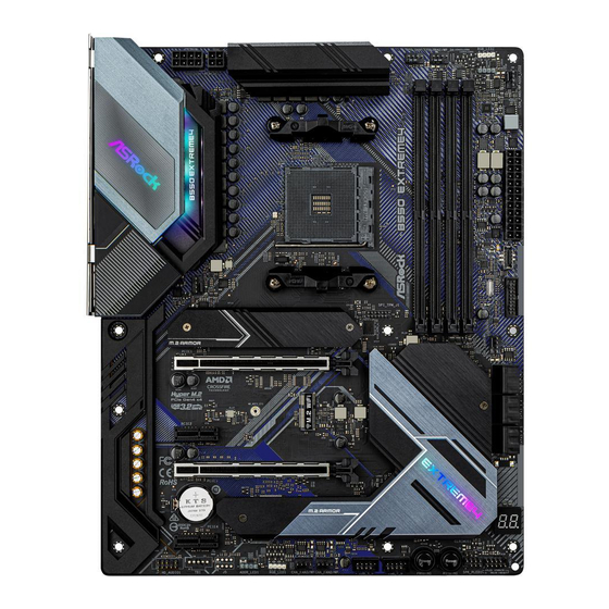
Page 14: Motherboard Layout
1.3 Motherboard Layout... - Page 15 B550 Extreme4 No. Description ATX 12V Power Connector (ATX12V1) ATX 12V Power Connector (ATX12V2) CPU Fan Connector (CPU_FAN1) 2 x 288-pin DDR4 DIMM Slots (DDR4_A1, DDR4_B1) CPU/Water Pump Fan Connector (CPU_FAN2/WP_3A) 2 x 288-pin DDR4 DIMM Slots (DDR4_A2, DDR4_B2) RGB LED Header (RGB_LED2)
-
Page 16: I/O Panel
1.4 I/O Panel No. Description No. Description PS/2 Mouse/Keyboard Port Microphone (Pink) USB 3.2 Gen2 Type-A Port Optical SPDIF Out Port (USB31_TA_1) 2.5G LAN RJ-45 Port USB 2.0 Ports (USB_34)*** (Dragon RTL8125BG)* USB 3.2 Gen2 Type-C Port Central / Bass (Orange) (USB31_TC_1) Rear Speaker (Black) USB 2.0 Ports (USB_12) - Page 17 B550 Extreme4 ** If you use a 2-channel speaker, please connect the speaker’s plug into “Front Speaker Jack”. See the table below for connection details in accordance with the type of speaker you use. Audio Output Front Speaker Rear Speaker...
-
Page 18: Chapter 2 Installation
Chapter 2 Installation This is an ATX form factor motherboard. Before you install the motherboard, study the configuration of your chassis to ensure that the motherboard fits into it. Pre-installation Precautions Take note of the following precautions before you install motherboard components or change any motherboard settings. -
Page 19: Installing The Cpu
B550 Extreme4 2.1 Installing the CPU Unplug all power cables before installing the CPU. -
Page 21: Installing The Cpu Fan And Heatsink
B550 Extreme4 2.2 Installing the CPU Fan and Heatsink After you install the CPU into this motherboard, it is necessary to install a larger heatsink and cooling fan to dissipate heat. You also need to spray thermal grease between the CPU and the heatsink to improve heat dissipation. Make sure that the CPU and the heatsink are securely fastened and in good contact with each other. - Page 23 B550 Extreme4 Installing the AM4 Box Cooler SR2...
- Page 25 B550 Extreme4 *The diagrams shown here are for reference only. The headers might be in a different position on your motherboard.
- Page 26 Installing the AM4 Box Cooler SR3...
- Page 27 B550 Extreme4...
- Page 28 +12V *The diagrams shown here are for reference only. The headers might be in a different position on your motherboard.
-
Page 29: Installing Memory Modules (Dimm)
B550 Extreme4 2.3 Installing Memory Modules (DIMM) This motherboard provides four 288-pin DDR4 (Double Data Rate 4) DIMM slots, and supports Dual Channel Memory Technology. 1. For dual channel configuration, you always need to install identical (the same brand, speed, size and chip-type) DDR4 DIMM pairs. - Page 30 Ryzen Series APUs (Renoir): UDIMM Memory Slot Frequency (Mhz) 3200 3200 3200 3200 2933 SR/DR SR/DR 2667 SR/DR SR/DR SR/DR SR/DR 2667 SR: Single rank DIMM, 1Rx4 or 1Rx8 on DIMM module label DR: Dual rank DIMM, 2Rx4 or 2Rx8 on DIMM module label...
- Page 31 B550 Extreme4 The DIMM only fits in one correct orientation. It will cause permanent damage to the motherboard and the DIMM if you force the DIMM into the slot at incorrect orientation.
-
Page 32: Expansion Slots (Pci Express Slots)
2.4 Expansion Slots (PCI Express Slots) There are 4 PCI Express slots on the motherboard. Before installing an expansion card, please make sure that the power supply is switched off or the power cord is unplugged. Please read the documentation of the expansion card and make necessary hardware settings for the card before you start the installation. -
Page 33: Jumpers Setup
B550 Extreme4 2.5 Jumpers Setup The illustration shows how jumpers are setup. When the jumper cap is placed on the pins, the jumper is “Short”. If no jumper cap is placed on the pins, the jumper is “Open”. Clear CMOS Jumper... -
Page 34: Onboard Headers And Connectors
2.6 Onboard Headers and Connectors Onboard headers and connectors are NOT jumpers. Do NOT place jumper caps over these headers and connectors. Placing jumper caps over the headers and connectors will cause permanent damage to the motherboard. System Panel Header Connect the power PLED+ PLED-... - Page 35 B550 Extreme4 Serial ATA3 Connectors These six SATA3 (SATA3_1: connectors support SATA see p.8, No. 15) data cables for internal (SATA3_2: storage devices with up to see p.8, No. 14) 6.0 Gb/s data transfer rate. (SATA3_3: *M2_2 and SATA3_5_6 see p.8, No. 16) share lanes.
- Page 36 Front Panel Audio Header This header is for PRESENCE# (9-pin HD_AUDIO1) MIC_RET connecting audio devices OUT_RET (see p.8, No. 31) to the front audio panel. OUT2_L J_SENSE OUT2_R MIC2_R MIC2_L 1. High Definition Audio supports Jack Sensing, but the panel wire on the chassis must support HDA to function correctly.
- Page 37 B550 Extreme4 CPU Water Pump Fan This motherboard FAN_SPEED_CONTROL CPU_FAN_SPEED Connector provides a 4-Pin water FAN_VOLTAGE (4-pin CPU_FAN2/ cooling CPU fan WP_3A) connector. If you plan (see p.8, No. 5) to connect a 3-Pin CPU water cooler fan, please connect it to Pin 1-3.
- Page 38 SPI TPM Header This connector supports SPI SPI_DQ3 +3.3V (13-pin SPI_TPM_J1) Trusted Platform Module (TPM) Dummy SPI_MOSI (see p.8, No. 32) system, which can securely store RST# TPM_PIRQ keys, digital certificates, pass- words, and data. A TPM system also helps enhance network SPI_TPM_CS# RSMRST# security, protects digital...
-
Page 39: Smart Switches
B550 Extreme4 2.7 Smart Switches The motherboard has two smart switches: Power Button and Reset Button, allowing users to quickly turn on/off the system or reset the system. Power Button Power Button allows users (PWRBTN1) to quickly turn on/off the Power (see p.8, No. -
Page 40: Dr. Debug
2.8 Dr. Debug Dr. Debug is used to provide code information, which makes troubleshooting even easier. Please see the diagrams below for reading the Dr. Debug codes. Code Description 0x10 PEI_CORE_STARTED 0x11 PEI_CAR_CPU_INIT 0x15 PEI_CAR_NB_INIT 0x19 PEI_CAR_SB_INIT 0x31 PEI_MEMORY_INSTALLED 0x32 PEI_CPU_INIT 0x33 PEI_CPU_CACHE_INIT... - Page 41 B550 Extreme4 0x63 DXE_CPU_INIT 0x68 DXE_NB_HB_INIT 0x69 DXE_NB_INIT 0x6A DXE_NB_SMM_INIT 0x70 DXE_SB_INIT 0x71 DXE_SB_SMM_INIT 0x72 DXE_SB_DEVICES_INIT 0x78 DXE_ACPI_INIT 0x79 DXE_CSM_INIT 0x90 DXE_BDS_STARTED 0x91 DXE_BDS_CONNECT_DRIVERS 0x92 DXE_PCI_BUS_BEGIN 0x93 DXE_PCI_BUS_HPC_INIT 0x94 DXE_PCI_BUS_ENUM 0x95 DXE_PCI_BUS_REQUEST_RESOURCES 0x96 DXE_PCI_BUS_ASSIGN_RESOURCES 0x97 DXE_CON_OUT_CONNECT 0x98 DXE_CON_IN_CONNECT...
- Page 42 0x99 DXE_SIO_INIT 0x9A DXE_USB_BEGIN 0x9B DXE_USB_RESET 0x9C DXE_USB_DETECT 0x9D DXE_USB_ENABLE 0xA0 DXE_IDE_BEGIN 0xA1 DXE_IDE_RESET 0xA2 DXE_IDE_DETECT 0xA3 DXE_IDE_ENABLE 0xA4 DXE_SCSI_BEGIN 0xA5 DXE_SCSI_RESET 0xA6 DXE_SCSI_DETECT 0xA7 DXE_SCSI_ENABLE 0xA8 DXE_SETUP_VERIFYING_PASSWORD 0xA9 DXE_SETUP_START 0xAB DXE_SETUP_INPUT_WAIT 0xAD DXE_READY_TO_BOOT 0xAE DXE_LEGACY_BOOT...
- Page 43 B550 Extreme4 0xAF DXE_EXIT_BOOT_SERVICES 0xB0 RT_SET_VIRTUAL_ADDRESS_MAP_BEGIN 0xB1 RT_SET_VIRTUAL_ADDRESS_MAP_END 0xB2 DXE_LEGACY_OPROM_INIT 0xB3 DXE_RESET_SYSTEM 0xB4 DXE_USB_HOTPLUG 0xB5 DXE_PCI_BUS_HOTPLUG 0xB6 DXE_NVRAM_CLEANUP 0xB7 DXE_CONFIGURATION_RESET 0xF0 PEI_RECOVERY_AUTO 0xF1 PEI_RECOVERY_USER 0xF2 PEI_RECOVERY_STARTED 0xF3 PEI_RECOVERY_CAPSULE_FOUND 0xF4 PEI_RECOVERY_CAPSULE_LOADED 0xE0 PEI_S3_STARTED 0xE1 PEI_S3_BOOT_SCRIPT 0xE2 PEI_S3_VIDEO_REPOST...
- Page 44 0xE3 PEI_S3_OS_WAKE 0x50 PEI_MEMORY_INVALID_TYPE 0x53 PEI_MEMORY_NOT_DETECTED 0x55 PEI_MEMORY_NOT_INSTALLED 0x57 PEI_CPU_MISMATCH 0x58 PEI_CPU_SELF_TEST_FAILED 0x59 PEI_CPU_NO_MICROCODE 0x5A PEI_CPU_ERROR 0x5B PEI_RESET_NOT_AVAILABLE 0xD0 DXE_CPU_ERROR 0xD1 DXE_NB_ERROR 0xD2 DXE_SB_ERROR 0xD3 DXE_ARCH_PROTOCOL_NOT_AVAILABLE 0xD4 DXE_PCI_BUS_OUT_OF_RESOURCES 0xD5 DXE_LEGACY_OPROM_NO_SPACE 0xD6 DXE_NO_CON_OUT 0xD7 DXE_NO_CON_IN...
- Page 45 B550 Extreme4 0xD8 DXE_INVALID_PASSWORD 0xD9 DXE_BOOT_OPTION_LOAD_ERROR 0xDA DXE_BOOT_OPTION_FAILED 0xDB DXE_FLASH_UPDATE_FAILED 0xDC DXE_RESET_NOT_AVAILABLE 0xE8 PEI_MEMORY_S3_RESUME_FAILED 0xE9 PEI_S3_RESUME_PPI_NOT_FOUND 0xEA PEI_S3_BOOT_SCRIPT_ERROR 0xEB PEI_S3_OS_WAKE_ERROR...
-
Page 46: Tm Operation Guide
2.9 CrossFireX and Quad CrossFireX Operation Guide This motherboard supports CrossFireX and Quad CrossFireX that allows you to install up to three identical PCI Express x16 graphics cards. 1. You should only use identical CrossFireX -ready graphics cards that are AMD certified. - Page 47 B550 Extreme4 Step 3 Connect a VGA/DVI/DP/HDMI cable from the monitor to the corresponding port on the graphics card installed to the PCIE1 slot.
-
Page 48: Driver Installation And Setup
2.9.2 Driver Installation and Setup Step 1 Power on your computer and boot into OS. Step 2 Remove the AMD drivers if you have any VGA drivers installed in your system. The Catalyst Uninstaller is an optional download. We recommend using this utility to uninstall any previously installed Catalyst drivers prior to installation. -
Page 49: Wifi/Bt Module Installation Guide (M2_Wifi_1)
B550 Extreme4 2.10 M.2 WiFi/BT Module Installation Guide (M2_WIFI_1) The M.2, also known as the Next Generation Form Factor (NGFF), is a small size and versatile card edge connector that aims to replace mPCIe and mSATA. The M.2 Socket (Key E) supports type 2230 WiFi/BT module. - Page 50 Step 3 Gently insert the WiFi/BT module into the M.2 slot. Please be aware that the module only fits in one orientation. Step 4 Tighten the screw with a screwdriver to secure the module into place. Please do not overtighten the screw as this might damage the module.
- Page 51 B550 Extreme4 2.11 M.2_SSD (NGFF) Module Installation Guide (M2_1) The M.2, also known as the Next Generation Form Factor (NGFF), is a small size and versatile card edge connector that aims to replace mPCIe and mSATA. The Hyper M.2 Socket (M2_1) supports M Key type 2230/2242/2260/2280 M.2 PCI Express module up to Gen4x4 (64 Gb/s) (with Matisse) or Gen3x4 (32 Gb/s) (with Renoir).
- Page 52 Step 3 Before installing a M.2 (NGFF) SSD module, please loosen the screws to remove the M.2 heatsink. *Please remove the protective films on the bottom side of the M.2 heatsink before you install a M.2 SSD module. Step 4 Prepare the M.2 standoff that comes with the package.
- Page 53 B550 Extreme4 M.2_SSD (NGFF) Module Support List Vendor Interface SanDisk PCIe SanDisk-SD6PP4M-128G( Gen2 x2) Intel PCIe INTEL 6000P-SSDPEKKF256G7 (nvme) Intel PCIe INTEL 6000P-SSDPEKKF512G7 (nvme) Intel PCIe SSDPEKKF512G7 NVME / 512GB Kingston PCIe Kingston SHPM2280P2 / 240G (Gen2 x4) Samsung PCIe...
-
Page 54: M.2_Ssd (Ngff) Module Installation Guide (M2_2)
2.12 M.2_SSD (NGFF) Module Installation Guide (M2_2) The M.2, also known as the Next Generation Form Factor (NGFF), is a small size and versatile card edge connector that aims to replace mPCIe and mSATA. The M.2 Socket (M2_2) supports M Key type 2230/2242/2260/2280/22110 M.2 SATA3 6.0 Gb/s module and M.2 PCI Express module up to Gen3 x2 (16 Gb/s). - Page 55 B550 Extreme4 Step 3 Before installing a M.2 (NGFF) SSD module, please loosen the screws to remove the M.2 heatsink. *Please remove the protective films on the bottom side of the M.2 heatsink before you install a M.2 SSD module.
- Page 56 Transcend TS256GMTS800-256GB Transcend SATA TS512GMTS800 / 512GB V-Color SATA V-Color 120G V-Color SATA V-Color 240G SATA WD GREEN WDS240G1G0B-00RC30 PCIe WDS512G1X0C-00ENX0 (NVME) / 512GB For the latest updates of M.2_SSD (NFGG) module support list, please visit our website for details: http://www.asrock.com...
-
Page 57: Chapter 3 Software And Utilities Operation
B550 Extreme4 Chapter 3 Software and Utilities Operation 3.1 Installing Drivers The Support CD that comes with the motherboard contains necessary drivers and useful utilities that enhance the motherboard’s features. Running The Support CD To begin using the support CD, insert the CD into your CD-ROM drive. The CD automatically displays the Main Menu if “AUTORUN”... -
Page 58: Asrock Motherboard Utility (A-Tuning)
3.2.1 Installing ASRock Motherboard Utility (A-Tuning) ASRock Motherboard Utility (A-Tuning) can be downloaded from ASRock Live Update & APP Shop. After the installation, you will find the icon “ASRock Mother- board Utility (A-Tuning)“ on your desktop. Double-click the “ASRock Motherboard Utility (A-Tuning)“... - Page 59 B550 Extreme4 OC Tweaker Configurations for overclocking the system. System Info View information about the system. *The System Browser tab may not appear for certain models.
- Page 60 Settings Configure ASRock ASRock Motherboard Utility (A-Tuning). Click to select "Auto run at Windows Startup" if you want ASRock Motherboard Utility (A-Tuning) to be launched when you start up the Windows operating system.
-
Page 61: Asrock Live Update & App Shop
Double-click on your desktop to access ASRock Live Update & APP Shop utility. *You need to be connected to the Internet to download apps from the ASRock Live Update & APP Shop. 3.3.1 UI Overview Category Panel Hot News... -
Page 62: Apps
3.3.2 Apps When the "Apps" tab is selected, you will see all the available apps on screen for you to download. Installing an App Step 1 Find the app you want to install. The most recommended app appears on the left side of the screen. The other various apps are shown on the right. - Page 63 B550 Extreme4 Step 3 If you want to install the app, click on the red icon to start downloading. Step 4 When installation completes, you can find the green "Installed" icon appears on the upper right corner. To uninstall it, simply click on the trash can icon...
- Page 64 Upgrading an App You can only upgrade the apps you have already installed. When there is an available new version for your app, you will find the mark of "New Version" appears below the installed app icon. Step 1 Click on the app icon to see more details. Step 2 Click on the yellow icon to start upgrading.
-
Page 65: Bios & Drivers
B550 Extreme4 3.3.3 BIOS & Drivers Installing BIOS or Drivers When the "BIOS & Drivers" tab is selected, you will see a list of recommended or critical updates for the BIOS or drivers. Please update them all soon. Step 1 Please check the item information before update. -
Page 66: Setting
3.3.4 Setting In the "Setting" page, you can change the language, select the server location, and determine if you want to automatically run the ASRock Live Update & APP Shop on Windows startup. -
Page 67: Nahimic Audio
B550 Extreme4 3.4 Nahimic Audio Nahimic audio software provides an incredible high definition sound technology which boosts the audio and voice performance of your system. Nahimic Audio interface is composed of four tabs : Audio, Microphone, Sound Tracker and Settings. -
Page 68: Asrock Polychrome Sync
3.5 ASRock Polychrome SYNC ASRock Polychrome SYNC is a lighting control utility specifically designed for unique indi- viduals with sophisticated tastes to build their own stylish colorful lighting system. Simply by connecting the LED strip, you can customize various lighting schemes and patterns, including Static, Breathing, Strobe, Cycling, Music, Wave and more. - Page 69 B550 Extreme4 Connecting the Addressable RGB LED Strip Connect your Addressable RGB LED strips to the Addressable LED Headers (ADDR_LED1, ADDR_LED2) on the motherboard. ADDR_LED2 DO_ADDR DO_ADDR VOUT VOUT ADDR_LED1 DO_ADDR VOUT 1. Never install the RGB LED cable in the wrong orientation; otherwise, the cable may be damaged.
- Page 70 ASRock Polychrome SYNC Utility Now you can adjust the RGB LED color through the ASRock Polychrome SYNC Utility. Download this utility from the ASRock Live Update & APP Shop and start coloring your PC style your way! Drag the tab to customize your preference.
-
Page 71: Chapter 4 Uefi Setup Utility
B550 Extreme4 Chapter 4 UEFI SETUP UTILITY 4.1 Introduction This section explains how to use the UEFI SETUP UTILITY to configure your system. You may run the UEFI SETUP UTILITY by pressing <F2> or <Del> right after you power on the computer, otherwise, the Power-On-Self-Test (POST) will continue with its test routines. -
Page 72: Navigation Keys
4.1.2 Navigation Keys Use < > key or < > key to choose among the selections on the menu bar, and use < > key or < > key to move the cursor up or down to select items, then press <Enter>... -
Page 73: Main Screen
B550 Extreme4 4.2 Main Screen When you enter the UEFI SETUP UTILITY, the Main screen will appear and display the system overview. -
Page 74: Oc Tweaker Screen
4.3 OC Tweaker Screen In the OC Tweaker screen, you can set up overclocking features. Because the UEFI software is constantly being updated, the following UEFI setup screens and descriptions are for reference purpose only, and they may not exactly match what you see on your screen. - Page 75 B550 Extreme4 CCD0 CCX0 Frequency (MHz) Use this item to adjust CCX0 Frequency. CCX1 Frequency (MHz) Use this item to adjust CCX1 Frequency. CCD1 CCX0 Frequency (MHz) Use this item to adjust CCX0 Frequency. CCX1 Frequency (MHz) Use this item to adjust CCX1 Frequency.
- Page 76 the appropriate frequency automatically. Setting DRAM Frequency can adjust DRAM Timing. DRAM Voltage Configure the voltage for the DRAM Voltage. Infinity Fabric Frequency and Dividers AMD Overclocking Setup Set Infinity Fabric frequency (FCLK). Auto: FCLK = MCLK. Manual: FCLK must be less than or equal to MCLK for best performance in most cases. Latency penalties are incurred if FCLK and MCLK are mismatched, but sufficiently high MCLK can negate or overcome this penalty.
- Page 77 B550 Extreme4 CPU VDD 1.8 Voltage Configure the voltage for the CPU VDD 1.8 PROM. Save User Default Type a profile name and press enter to save your settings as user default. Load User Default Load previously saved user defaults.
-
Page 78: Advanced Screen
4.4 Advanced Screen In this section, you may set the configurations for the following items: CPU Configuration, Onboard Devices Configuration, Storage Configuration, ACPI Configuration, Trusted Computing , AMD PBS, AMD Overclocking and AMD CBS. Setting wrong values in this section may cause the system to malfunction. UEFI Configuration Active Page on Entry Select the default page when entering the UEFI setup utility. -
Page 79: Cpu Configuration
B550 Extreme4 4.4.1 CPU Configuration PSS Support Use this to enable or disable the generation of ACPI_PPC, _PSS, and _PCT objects. NX Mode Use this to enable or disable NX mode. SVM Mode When this is set to [Enabled], a VMM (Virtual Machine Architecture)can utilize the additional hardware capabilities provided by AMD-V. -
Page 80: Onboard Devices Configuration
4.4.2 Onboard Devices Configuration Turn On Onboard LED in S5 Turn on/off the LED in the ACPI S5 state. SR-IOV Support Enable/disable the SR-IOV (Single Root IO Virtualization Support) if the system has SR-IOV capable PCIe devices. UMA Frame buffer Size (Only for processor with integrated graphics) This item allows you to set the size of the UMA frame buffer. - Page 81 B550 Extreme4 WAN Radio Configure the WiFi module's connectivity. BT On/Off Enable/disable the bluetooth. Onboard LAN Enable or disable the onboard network interface controller. PS2 Y-Cable Enable the PS2 Y-Cable or set this option to Auto.
-
Page 82: Storage Configuration
4.4.3 Storage Configuration SATA Mode AHCI: Supports new features that improve performance. RAID: Combine multiple disk drives into a logical unit. SATA Hot Plug Enable/disable the SATA Hot Plug function. -
Page 83: Acpi Configuration
B550 Extreme4 4.4.4 ACPI Configuration Suspend to RAM It is recommended to select auto for ACPI S3 power saving. Deep Sleep Configure deep sleep mode for power saving when the computer is shut down. We recommend disabling Deep Sleep for better system compatibility and stability. -
Page 84: Trusted Computing
4.4.5 Trusted Computing Security Device Support Enable or disable BIOS support for security device. -
Page 85: Amd Pbs
B550 Extreme4 4.4.6 AMD PBS The AMD PBS menu accesses AMD specific features. -
Page 86: Amd Overclocking
4.4.7 AMD Overclocking The AMD Overclocking menu accesses options for configuring CPU frequency and voltage. - Page 87 B550 Extreme4 4.4.8 AMD CBS The AMD CBS menu accesses AMD specific features.
- Page 88 4.5 Tools Easy RAID Installer Easy RAID Installer helps you to copy the RAID driver from the support CD to your USB storage device. After copying the drivers please change the SATA mode to RAID, then you can start installing the operating system in RAID mode. SSD Secure Erase Tool All the SSD's listed that supports Secure Erase function.
- Page 89 B550 Extreme4 4.6 Hardware Health Event Monitoring Screen This section allows you to monitor the status of the hardware on your system, including the parameters of the CPU temperature, motherboard temperature, fan speed and voltage. CPU FAN1 Setting Select a fan mode for CPU Fan 1, or choose Customize to set 5 CPU temperatures and assign a respective fan speed for each temperature.
- Page 90 CPU Fan 2 Temp Source Select a fan temperature source for CPU Fan 2. CHA_FAN1/WP Switch Select CHA_FAN1 or Water Pump mode. Chassis Fan 1 Control Mode Select PWM mode or DC mode for Chassis Fan 1. Chassis Fan 1 Setting Select a fan mode for Chassis Fan 1, or choose Customize to set 5 CPU temperatures and assign a respective fan speed for each temperature.
- Page 91 B550 Extreme4 Chassis Fan 3 Temp Source Select a fan temperature source for Chassis Fan 3. CHA_FAN4/WP Switch Select CHA_FAN4 or Water Pump mode. Chassis Fan 4 Control Mode Select PWM mode or DC mode for Chassis Fan 4. Chassis Fan 4 Setting Select a fan mode for Chassis Fan 4, or choose Customize to set 5 CPU temperatures and assign a respective fan speed for each temperature.
- Page 92 4.7 Security Screen In this section you may set or change the supervisor/user password for the system. You may also clear the user password. Supervisor Password Set or change the password for the administrator account. Only the administrator has authority to change the settings in the UEFI Setup Utility. Leave it blank and press enter to remove the password.
- Page 93 B550 Extreme4 4.8 Boot Screen This section displays the available devices on your system for you to configure the boot settings and the boot priority. Boot From Onboard LAN Allow the system to be waked up by the onboard LAN.
- Page 94 CSM (Compatibility Support Module) Enable to launch the Compatibility Support Module. Please do not disable unless you’re running a WHCK test. Launch PXE OpROM Policy Select UEFI only to run those that support UEFI option ROM only. Select Legacy only to run those that support legacy option ROM only. Select Do not launch to not execute both legacy and UEFI option ROM.
- Page 95 B550 Extreme4 AddOn ROM Display Enable AddOn ROM Display to see the AddOn ROM messages or configure the AddOn ROM if you've enabled Full Screen Logo. Disable for faster boot speed.
- Page 96 4.9 Exit Screen Save Changes and Exit When you select this option the following message, “Save configuration changes and exit setup?” will pop out. Select [OK] to save changes and exit the UEFI SETUP UTILITY. Discard Changes and Exit When you select this option the following message, “Discard changes and exit setup?”...
- Page 97 Contact Information If you need to contact ASRock or want to know more about ASRock, you’re welcome to visit ASRock’s website at http://www.asrock.com; or you may contact your dealer for further information. For technical questions, please submit a support request form at http://www.asrock.com/support/tsd.asp...
- Page 98 13848 Magnolia Ave, Chino, CA91710 Phone/Fax No: +1-909-590-8308/+1-909-590-1026 hereby declares that the product Product Name : Motherboard B550 Extreme4 Model Number : Conforms to the following speci cations: FCC Part 15, Subpart B, Unintentional Radiators Supplementary Information: is device complies with part 15 of the FCC Rules. Operation is subject to the...
- Page 99 EU Declaration of Conformity For the following equipment: Motherboard (Product Name) B550 Extreme4 / ASRock (Model Designation / Trade Name) ASRock Incorporation (Manufacturer Name) 2F., No.37, Sec. 2, Jhongyang S. Rd., Beitou District, Taipei City 112, Taiwan (R.O.C.) (Manufacturer Address) EMC —Directive 2014/30/EU (from April 20th, 2016)
Need help?
Do you have a question about the B550 EXTREME4 and is the answer not in the manual?
Questions and answers