Table of Contents
Advertisement
Quick Links
Advertisement
Table of Contents

Related Manuals for Oval LS5076

Summary of Contents for Oval LS5076
- Page 1 Ins. No. Ins. No. ( ) ( ) 機械式計数部付 OIL SERVICE 油用フローペット FLOWPET WITH MECHANICAL REGISTER MODEL LS5376 - 2 □□ A パルス発信器なし パルス発信器付 without pulse generator with pulse generator...
-
Page 2: Table Of Contents
S-177-1 ( E) このたびは、フローペット-NX(NX:New Excellent)をご採用いただきましてありがとうございます。 本製品は、当社において厳重な品質管理の下に製造出荷されております。正しくお使いいただくため、本書では 取り扱いに当たって、必要な注意事項を記載してあります。 ご使用の前にこの取扱説明書をよくお読みいただきますようお願いいたします。 また、本書は大切に保管してください。 目 次 1.取り扱い上の注意 ....................4 6.運 転 ........................27 1.1 ネームプレートの確認 ................5 6.1運転上の注意 ....................27 1.2 運搬についての注意事項 ..............6 7.故障対策 .........................30 1.3 保管についての注意事項 ..............7 8.分解点検要領 ......................32 1.4 設置場所の注意事項 ................. 8 8.1 本体部の分解点検 .................32 2.使用条件........................ - Page 3 S-177-1 ( E) Thank you for choosing OVAL's Flowpet-NX (NX for New Excellent). All our products are manufactured, tested, and shipped from our factory under rigorous quality control. This manual is designed to assist the user to obtain the best performace of this product throughout its service life.
-
Page 4: 1.取り扱い上の注意
S-177-1 ( E) 1.取扱い上の注意 1. HANDLING PRECAUTIONS Every Flowpet is thoroughly tested and inspected 本器は工場で十分な検査をして出荷されております。 before shipment from our factory. When received, 本器がお手もとへ届きましたら、 外観をチェックして、 inspect the appearance of the product and make 損傷の無いことをご確認ください。 sure that there is no damage incurred by rough 本項では取扱いに当って必要な注意事項を記載して... -
Page 5: ネームプレートの確認
S-177-1 ( E) S-177-1 ( E) 1.1 ネームプレートの確認 1.1 Confirming the Nameplate フローペットは、1台づつ仕様に合わせ出荷されて The Flowpet is adjusted to individual specifications before shipment from our factory. Indicated on おります。 the register nameplate are the product code 計数部上面のネームプレートに製品番号および定格 number and ratings. Make sure that the Product 仕様が記載されています。10頁の製品番号および38頁... -
Page 6: 運搬についての注意事項
S-177-1 ( E) S-177-1 ( E) S-177-1 ( E) 1.2 運搬についての注意事項 1.2 Transportation Precautions (1) In order to safeguard against damage during (1)運搬中の事故により損傷することを防ぐためフロー transportation, transport your Flowpet to the ペットはなるべく当社から出荷したときの包装状 installation location in the style packaged from 態で設置場所まで運んでください。 our factory if possible. (2)本器は、本体部-計数部-発信器の全てを一体と... -
Page 7: 保管についての注意事項
S-177-1 ( E) 1.3 保管についての注意事項 1.3 Storage Precautions If the Flowpet is to be stored over an extended フローペットがお手もとへ届いた後、設置までの期 period of time before installation, make sure to take 間が長いと、思いがけぬことから故障が生じることが following precautions to avoid unexpected damages: 考えられます。あらかじめ長時間の保管が予想される (1) The Flowpet should be stored in the style 場合は、以下の項目にご注意ください。... -
Page 8: 設置場所の注意事項
S-177-1 ( E) 1.4 設置場所の注意事項 1.4 Installation Location Precautions (1) When lagging is necessary, the register, strainer (1)保温工事を施す場合、計数部、ストレーナ蓋、ド cover and drain plug should not be lagged, レン抜きプラグは、 保温しないでください。なお、 however. Also, make sure that the meter can be 流量計は、配管より容易に分離できるよう考慮し separated readily from the piping assembly. てください。... -
Page 9: 2.使用条件
3. 概要 3. GENERAL DESCRIPTION (1) Precise flow measurement can be achieved by (1)オーバル流量計本来の高い精度を発揮し、正確な nature of the Oval positive displacement meter. 流量計測が可能です。 (2) Direct-readout type counter is specifically (2)直読積算計数部は、シンプルなデザインで、機能 designed for function and legibility first. -
Page 10: 製品記号の説明
されています。 製品形式 Code 説 明 Description ① ② ③ ④ ⑤ ⑥ - ⑦ ⑧ ⑨ ⑩ 機種 Model 専用オーバル流量計 Dedicated Oval Flowmeter 20A JIS 10K RF 25A JIS 10K RF 容量形式 40A JIS 10K RF Meter Size 40A JIS 10K RF 50A JIS 10K RF 機種名 Model Name... -
Page 11: 各部の名称
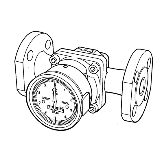
S-177-1 ( E) S-177-1 ( E) 3.2 各部の名称 Part Names 流入方向矢印 FLOW DIRECTION ARROW 本体部 METER BODY 発信器 PULSE GENERATOR ケーブルコネクタ CABLE CONNECTOR 指 針 〈パルス発信器付〉 POINTER with pulse generator 接続フランジ 累積積算計ドラム (6桁) 機械式計数部 FLANGE TOTAL COUNTER MECHANICAL DRUM(6 digits) REGISTER 〈パルス発信器なし〉... -
Page 12: 4.配管要領
S-177-1 ( E) 4. 配管要領 4. PIPING 4.1 配管上の注意 4.1 Piping Precautions (1) Install the meter, exercising care to avoid pipe (1)配管歪みを与えないようフランジボルトを無理に strains. 締め付けないように取り付けてください。 (2) The meter should be installed downstream of the (2)流量計はポンプの出口側に取り付けてください。 pump. (3)ストレーナを流量計の上流側に設置してください。 (3) Provide a strainer upstream of the meter. なお、ストレーナのネットは定期的に洗浄する必... - Page 13 形 式 Model Model 灯 油 1.2 mPa ・ s 重 油 19 mPa ・ s 灯 油 1.2mPa ・ s 重 油 19mPa ・ s Kerosene Heavy Oil Kerosene Heavy Oil LS5076 14 (1600L/h) 40 (2000L/h) LS5076 14(1600L/h) 40(2000L/h) LS5276 13 (3000L/h) 56 (3800L/h) LS5276 13(3000L/h)...
- Page 14 よび強磁界を発生する導線から離した場所に、設 powerful magnets and conductors creating 置してください。 strong magnetic fields. (7)電気加温をする場合は、 当社までご相談ください。 (7) If electric heating is desired, consult OVAL. (8)配管の気密試験を実施する際は、空気の暴走によ (8) When you conduct a gastight test on the existing る回転子破損を防止するため、慎重なバルブ操作 piping assembly, careful valve operations が必要です。...
-
Page 15: 配管をフラッシングする場合
S-177-1 ( E) 4.2 配管をフラッシングする場合 4.2 Flushing the Piping Assembly ◆ Be sure to remove the meter from the piping ◆必ず配管から流量計を取り外し、短管を挿入して行 ってください。 assembly and install a short pipe section in place of the meter. 流量計を取り付けた状態でフラッシングを実施しま Flushing the piping assembly with the meter in すと、計量室に重大な損傷を生じます。必ず、流量計... -
Page 16: 保温工事上の注意
S-177-1 ( E) 4.3 保温工事上の注意 4.3 Lagging Work Precautions 寒冷地で使用し凍結の心配のある場 For applications where the meter is to be placed in service in cold regions or where 合、凝固性の液体を計量する場合な solidifying materials are to be metered, どは、流量計・ストレーナの保温工 lagging work for the flowmeter and 事を行うことをおすすめします。... -
Page 17: 配管例
S-177-1 ( E) S-177-1 ( E) S-177-1 ( E) 4.4 配 管 例 Examples of Installation 〈垂直配管〉 (注記)⇨12頁の“配管上の注意”に従って配管してください。 配管上部より落下するスケールを防ぐた ⇨外形寸法図は44頁参照 め、バイパス側に取り付けてください。 NOTE: Make pipe connections following the instructions Vertical Line ● under the topic " Piping Precautions" on page 12. Install on the bypass side to prevent For outline dimensions, see page 44. - Page 18 S-177-1 ( E) S-177-1 ( E) 〈誤った配管例〉 Example of Incorrect Piping ● ◎下図のような流量計の取り付け方をしないよう注意してください。 (計量室が水平に設置されるのが正しい取り付け方です。 ) Do not install the meter in a position like the diagram below. (Installation is correct if the measuring chamber is on a level plane.) ストレーナ STRAINER フローペット-NX 誤り...
-
Page 19: 流入方向の変更方法
S-177-1 ( E) S-177-1 ( E) S-177-1 ( E) S-177-1 ( E) 4.5 流入方向の変更方法 4.5 How to Change the Flow Directions ● 出荷時のフローペットの流入方向は右から左に組 ● The Flowpet is so assembled to accept the flow み付けられています。変更する場合は次の方法で from right to left. Flow directions can simply and 容易に変更可能です。... -
Page 20: 5.配線要領
S-177-1 ( E) 5. 配線要領 5. WIRING In case of the pulse generator equipped Model LS パルス発信器付MODEL LS □ □ 76-2 □ □ Aの場 □ □ 76- 2 □ □ A, make electrical connections as 合は、次の要領で配線をしてください。 follows. Also refer to the instruction manual for また、配線に当たっては、受信器の取扱説明書(配... -
Page 21: 結線図
S-177-1 ( E) 5.2 結線図 Wiring Diagrams (注記)結線要領は23~26頁をご覧ください。 NOTE: For wiring connections, see pages 23 to 26. ■オープンコレクタパルス出力の場合 Open Collector Pulse Output (MODEL LS □ □ 76-2 □ 1A) 受信器 RECEIVER (注記)負荷抵抗R の値は、Eとの関係により電流が 30mA以下となるように選定してください。 E≦40VDC 12〜24VDC± 1 0% フローペッ ト 発信器 1≦30mA FLOWPET GENERATOR... - Page 22 S-177-1 ( E) ■接点パルス出力の場合 Contact-closure Pulse Output (MODEL LS □ □ 76-2 □ 3A) 発信器 RECEIVER 200Ω SIG1 最大使用電圧 Max. Voltage 125VAC、 5VDC SIG2 フローペッ ト 発信器 最大使用電流 Max. Current FLOWPET 60mA GENERATOR (注記)ケーブル線間容量によるサージ電流を防止し、接点寿命を長く保つために接点保護用の直列抵抗(200Ω) の接続を標準としますが、SIG2 ~ COMに配線することにより直列抵抗器を接続せずに使用することも できます。 NOTE: To prevent current surges due to interlead capacitance of the cable and prolong contact life, a series 200Ω...
-
Page 23: 結線要領
S-177-1 ( E) 5.3 結線要領 Wiring Connections 5.3.1 端子説明 Terminal Identification パルス発信器付の場合、端子台への結線は出力形式により下記の3種類があります。 On pulse generator equipped models, wiring connections at the terminal block come in the following three types, depending on the type of output: 端 子 番 号 出 力 形 式 製品記号... -
Page 24: 端子への結線
S-177-1 ( E) S-177-1 ( E) S-177-1 ( E) 5.3.2 端子への結線 Connections to Terminals 本器のケーブルコネクタを取り外し、リード線をケーブルコネクタの内器(端子台)に結線してください。 Uncouple the cable connector and connect lead wires to the internal assembly of the cable connector (terminal block). ① ケーブルコネクタ固定ねじをプラスドライバでゆるめて から、ケーブルコネクタを引き抜いて、発信器より分離 します。 Loosening the cable connector fitting screw, using screwdriver, remove the cable connector and separate it form the pulse generator. - Page 25 S-177-1 ( E) S-177-1 ( E) S-177-1 ( E) ③ ケーブルコネクタのケーブル固定ねじ、座金、ゴムパッキン Connector Cover を外して、ケーブルに順に通してからケーブルをコネクタカ コネクタカバー バーに入れ、端子台側に引き出します。 Remove the cable fitting screw, washer, rubber packing of the cable connector, slip them in this order on the cable, 固定ねじ then pass the cable into the connector cover and out Fitting through its opening to the terminal block.
- Page 26 S-177-1 ( E) S-177-1 ( E) ⑤ 結線済端子台を、コネクタカバーに入れ、端子台 ⑦ ケーブルコネクタを計数部発信器側プラグに差し のロックボスが「カチッ」と音がするまで押し込 込んで、ケーブルコネクタ固定ねじを締めて組立 み固定します。 完了です。 Install the terminal block which has been wired Install the cable connector into its plug at the into the connector cover and secure it by register pulse generator end and secure it with pressing in until the lock boss snaps in.
-
Page 27: 目 次 6.運 転
S-177-1 ( E) 6. 運転 OPERATION 6.1 運転上の注意 Note on Operation (1)運転前にネームプレート記載事項を読み、使用条件が仕様に適合しているか確認してください。 また、設置方法、配管接続、配線に誤りがないか、確認してください。 Read the information given on the nameplate before commencing operation and make sure to see the operating conditions conform to the specifications. Also make certain that meter installation, pipeline connections and electrical wiring have been made correctly. - Page 28 S-177-1 ( E) 〈注意〉 CAUTION 特に80℃以上の高温液体でご使用になる場合は、この状態で10分以上運転し、計量室の熱分 布が均一になるようにしてください。 In case where the meter is used with heavy oil exceeding 80 ℃ in temperature, maintain this condition at least for 10 minutes to obtain uniform temperature distribution in the measuring chamber. ④ 予熱が終わったらバルブ(C)を徐々に閉め、 バルブ(A) 、 (B)を徐々に開き、 規定流量にしてください。 After a warmup period, slowly close the valve C and progressively open the valves A and B until the rated flow is reached.
- Page 29 S-177-1 ( E) S-177-1 ( E) (3)凝固し易い計量液の場合は、保温工事を行なってください。 〈保温工事は16頁参照〉 In applications where materials that tend to solidify are to be metered, lagging work is necessary. See page 16 for lagging work. (4)ストレーナは定期的にネットの点検、洗浄を実施してください。 特に、新設配管の場合は、最初1日に1回点検して目詰まり状態を観察し、次に2~3日に1回と点検頻度 を次第に下げてください。 The strainer net should be inspected and cleaned on a regular basis. On a newly installed piping assembly in particular, daily inspection of the net is necessary.
-
Page 30: 7.故障対策
S-177-1 ( E) 7. 故障対策 症 状 原 因 対 策 1.通液しない。 1.流量計のフランジ入口と出口の保護 1.流量計を外し、カバーを除去。 (積算値が少なすぎる。 ) カバーを外さないで配管した。 2.オーバル回転子にスケールが噛み込 2.計数部を分離し、本体部の分解、洗 み回転しなくなり、計量液が流れな 浄の実施。 いと考えられる場合。 3.ポンプ圧力またはヘッド圧が不足。 3.配管系全体の圧力損失を考慮し、適 正なポンプを選定。 〈配管要領12頁参照〉 2.液漏れがある。 1.シール部が不完全。 1.配管接続部の増し締め。 2.本体部蓋用Oリングの交換。 3.通液するが積算表示しない。 1.分解点検時正しく組み立てていない。 1.分解して正しく組立てる。 お願い !! ● 上記以外の故障と考えられる場合は、当社サービス網までご連絡ください。 その場合、製品名称、製品形式、症状などの詳細をお知らせください。... -
Page 31: Troubleshooting
2. Oval rotors have caught scales and 2. Separate the register, disassemble and fail to rotate, blocking the fluid flow. clean the meter body. 3. Pump pressure or head pressure is 3. -
Page 32: 8.分解点検要領
S-177-1 ( E) S-177-1 ( E) S-177-1 ( E) 8. 分解点検要領 DISASSEMBLY AND INSPECTION 8.1 本体部の分解点検 Meter Body Disassembly and Inspection 分解点検の際は、中に水やゴミが入らないようにご注意ください。 〈注意〉 分解前に温度を十分下げてください。流れ出入口から油抜きをしても、一部油の抜けにくい部分があります。 CAUTION: During disassembly and inspection, be extremely careful to keep moisture and dust out. Make sure to wait until the meter body cools down to a satisfaactory temperature. Also, remember that draining oil completely from its inlet/outlet may take some time. - Page 33 S-177-1 ( E) S-177-1 ( E) S-177-1 ( E) Eリング 上蓋 E-RING TOP COVER ピニオン 主動磁石付ホルダ PINION ビス HOLDER WITH 本体部 主動磁石歯車 SCREW DRIVING MAGNET METER BODY DRIVING MAGNET GEAR ③ 上蓋を取り外す前に、次の手順で主動磁石歯車を取り外します。 Before separating the top cover, remove the driving magnet gear in the following steps: 〈注意〉主動磁石歯車を軸に付けたまま、上蓋部を本体部から外さないでください。...
- Page 34 S-177-1 ( E) S-177-1 ( E) S-177-1 ( E) (注記)下図は、50、52、53形本体部の場合です。NOTE: Shown below are the compoents of sizes 50, 52, and 53. 上蓋 TOP COVER 回転子 ROTORS 押しタップねじ穴 THREADED JACK 上蓋締付ねじ Oリング SCREW HOLES TOP COVER SCREW O-RING ④ 上蓋を本体部より取り外します。 ⑤ 回転子を抜き取ります。計量室を点検し、各部の スケールを洗浄してください。...
-
Page 35: 組立上の注意
S-177-1 ( E) S-177-1 ( E) S-177-1 ( E) 組立上の注意 Precautions at Assembly 第2回転子 本体部 2ND ROTOR 組立は分解の逆となりますが、 特に次の点を注意してください。 METER BODY Assembly is the reverse order of disassembly. 流入方向 Observe the following instructions. FLOW (1)流入方向(計数部側から見た場合)が左から右の場合、第 DIRECTION 一回転子は下側になります。回転子は右図のように組み合 わせ、1回転以上手で回転させスムーズに回ることを確認 してから組み付けてください。第1回転子は、本体部の第 2回転子側へは入りません。 If the flow direction is from right to left (as viewed from 第1回転子(ピニオン付)... -
Page 36: 9.立体分解図およびサービス部品一覧表
S-177-1 ( E) S-177-1 ( E) 9. 立体分解図およびサービス部品一覧表 EXPLODED VIEW AND SERVICE PARTS LIST 〈立体分解図〉Exploded View SIZES 50, 52, 53 SIZES 55, 56 (注記)部品表は次頁をご覧ください。 NOTE: See the next page for parts list. -
Page 37: サービ部品一覧表
S-177-1 ( E) 〈サービス部品一覧表〉 〈Service Parts List〉 代表№ ユニット名称 部品名称 数量 備考 Assembly Name Part Name Q'ty Remarks 50、52、 本体 Basic Sizes 50, Meter Body 本体部 1set 1set 53形 回転子軸 Unit 52, 30 Rotor Shaft 本体 第2回転子軸付 Meter Body with 2nd rotor shaft Basic Sizes 55, 本体部... -
Page 38: 10.標準仕様
S-177-1 ( E) 10. 標準仕様 10.1 流量範囲 油 用 L/h 呼び径 容量形式 灯 油 軽 油(A重油) 重 油 150 ~ 1600 80 ~ 2000 50 ~ 2000 300 ~ 3000 150 ~ 3800 80 ~ 3800 600 ~ 5000 300 ~ 6400 150 ~ 6400 1200 ~... -
Page 39: General Specifications
S-177-1 ( E) 10. GENERAL SPECIFICATIONS 10.1 Flow Range Oil Service Nominal Dia. Size Kerosene Light Oil (A Heavy Oil) Heavy Oil 150 ~ 1600 80 ~ 2000 50 ~ 2000 300 ~ 3000 150 ~ 3800 80 ~ 3800 600 ~... -
Page 40: 計数部、発信器
塗 装 色(ケース) マンセル4.9PB 4.0/13.9相当(成形色) Mechanical Register ● Item Specifications Function Cumulative total counter with a dial-pointer and number drums Model LS5076, LS5276 LS5376, LS5576, LS5676 One pointer revolution Display Resolution 0.01L 0.1L Counter capacity 999,999.99L 9,999,999.9L Output Pulse See next section Operating Temp. - Page 41 Output Freq. Pulse Unit Output Freq. (mm) (L/h) (L/P) at Max. Rate (L/P) at Max. Rate (Hz) (Hz) LS5076-2 □ □ A 0.55 2000 LS5276-2 □ □ A 10.5 1.05 3800 LS5376-2 □ □ A 0.18 6400 LS5576-2 □ □ A 0.38...
- Page 42 S-177-1 ( E) 機械式計数部補正パルス発信器(オプション) ● 仕 様 項 目 MRセンサ リードスイッチ 出 力 パ ル ス 方 式 電圧パルス オープンコレクタ 接点パルス パルス数(指針一回転当たり) パ ル ス 幅 1ms以上 波 形 比 率 40/60 ~ 60/40 ON : 6.5V以上 出 力 信 号 電 圧...
- Page 43 S-177-1 ( E) Factored Pulse Generator (Option) in Mechanical Register ● Specifications Item MR Sensor Reed Switch Output Pulse Type Voltage pulse Open collector Contact-closure pulse Number of Pulse (per pointer rev.) Pulse Width 1ms min. Duty Factor 40/60 to 60/40 ON : 6.5V min.
-
Page 44: 11.外形寸法図
約86 86 approx. フランジ 呼び径 質量 製品記号 Flange Nominal Weight Model Dia. d P.C.D. n-φh LS5076-2 □ □ A 162.5 - - 117.5 4-15 LS5276-2 □ □ A 175.5 - - 120.5 4-19 LS5376-2 □ □ A 189.5 - -... -
Page 45: ストレーナ
P.C.D. n-φh Model Flange Rating Mesh Flowpet-NX SS5278A 20A JIS 10K RF 4-15 LS5076-2 □ □ A SS5378A 25A JIS 10K RF 4-19 LS5276-2 □ □ A LS5376-2 □ □ A SS5578A 40A JIS 10K RF 4-19 LS5576-2 □ □ A... - Page 46 S-177-1 ( E) 取扱説明書の記載内容は、性能・品質改良に伴い予告なく変更することがありますので、 ご了承ください。 2014. 04 改訂 Revised△ All specifications in this instruction manual are subject to change without notice for improvement 1998. 12 初版 Released in performance and product quality. S-177-1(E) (1)
Need help?
Do you have a question about the LS5076 and is the answer not in the manual?
Questions and answers