Table of Contents
Advertisement
Quick Links
SERVICE MANUAL
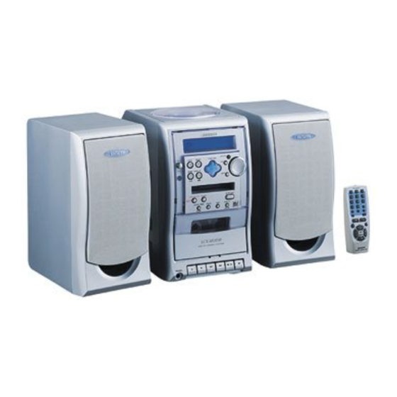
MD/CD STEREO SYSTEM
MODEL CODE : 8ACJB-0130(S)
8ACJB-0140(D)
8ACJB-0180(L)
SYSTEM
LCX-MD211
• This Service Manual is the “Revision Publishing” and replaces “Simple Manual”
LCX-MD210(D), LCX-MD211(EZ),(S/M Code No. 09-003-429-4T2).
All manuals and user guides at all-guides.com
SPEAKER
SX-MD210
S/M Code No. 09-007-429-4R2
LCX-MD211
BASIC TAPE MECHANISM : TN-21ZSC-2003
BASIC CD MECHANISM : DA11T3C
BASIC MD MECHANISM : AZG-4 A
REMOTE
CONTROLLER
RC-AAT11
EZ
Advertisement
Table of Contents

Related Manuals for Aiwa LCX-MD211


Summary of Contents for Aiwa LCX-MD211
- Page 1 BASIC MD MECHANISM : AZG-4 A MODEL CODE : 8ACJB-0130(S) 8ACJB-0140(D) 8ACJB-0180(L) REMOTE SYSTEM SPEAKER CONTROLLER LCX-MD211 SX-MD210 RC-AAT11 • This Service Manual is the “Revision Publishing” and replaces “Simple Manual” LCX-MD210(D), LCX-MD211(EZ),(S/M Code No. 09-003-429-4T2). S/M Code No. 09-007-429-4R2...
-
Page 2: Specifications
All manuals and user guides at all-guides.com SPECIFICATIONS MAIN UNIT Compact disc player section FM tuner section Laser Semiconductor laser (l = 780nm) D-A converter 1 bit linear Tuning range 87.5 MHz to 108 MHz Wow and flutter Unmeasureable Antenna terminals 75 ohms (unbalanced) MD recorder section MW tuner section... -
Page 3: Protection Of Eyes From Laser Beam During Servicing
All manuals and user guides at all-guides.com PROTECTION OF EYES FROM LASER BEAM DURING SERVICING CAUTION This set employs laser. Therefore, be sure to follow carefully the instructions below when servicing. Use of controls or adjustments or performance of proce- dures other than those specified herin may result in WARNING!! hazardous radiation exposure. -
Page 4: Disassembly Instruction
All manuals and user guides at all-guides.com DISASSEMBLY INSTRUCTION 1. Removing CD Mechanism, CHAS, CD 1-1. Remove 12 screws (BVT2+3-10). Pull the panel, L in the rear direction, and press it in the bottom direction to remove it. 1-2. Remove the panel, R in the same way as for L. 1-3. - Page 5 All manuals and user guides at all-guides.com 1-4. Release the tabs on both sides at the top of front cabinet, and lift the rear of CHAS, CD to remove the CHAS, CD, CD mechanism and CD C.B. in one unit. 2.
- Page 6 All manuals and user guides at all-guides.com 2-2. Remove two screws (BVT2+3-10) that fix the CHAS, MD to the CHAS, MAIN. 2-3. Remove two QT2+3-8 screws at the bottom of both sides of front cabinet. Remove two BVT2+3-10 screws from the bottom of CHAS, MAIN.
- Page 7 All manuals and user guides at all-guides.com 2-4. Release the tabs of front cabinet, and remove the CHAS, MAIN with the power transformer C.B. 2-5. Remove two screws (BVT2+3-10) that fix the CHAS, MD to the front cabinet. Disconnect the flat cables (14P, 18P) from the MD mechanism, and remove the sheets that hold the cables.
-
Page 8: Electrical Main Parts List
All manuals and user guides at all-guides.com ELECTRICAL MAIN PARTS LIST REF. NO. PART NO. KANRI DESCRIPTION REF. NO. PART NO. KANRI DESCRIPTION C204 87-010-197-080 CAP, CHIP 0.01 DM C225 87-010-401-080 CAP, ELECT 1-50V C226 87-010-401-080 CAP, ELECT 1-50V 87-A20-459-010 C-IC,LC78622ED 87-A21-213-010 IC,BA17808T... - Page 9 All manuals and user guides at all-guides.com REF. NO. PART NO. KANRI DESCRIPTION REF. NO. PART NO. KANRI DESCRIPTION C709 87-012-195-080 C-CAP,U 100P-50CH C862 87-012-199-080 CAP 220P C711 87-010-265-080 CAP, ELECT 33-16V C863 87-012-270-080 CAP, U 470P-50 C712 87-010-831-080 C-CAP,U,0.1-16F C864 87-010-405-080 CAP, ELECT 10-50V...
- Page 10 All manuals and user guides at all-guides.com REF. NO. PART NO. KANRI DESCRIPTION REF. NO. PART NO. KANRI DESCRIPTION C609 87-010-315-080 C-CAP,S 27P-50 CH C406 87-010-374-080 CAP, ELECT 47-10V C610 87-010-452-080 CAPACITOR,1-16 C407 87-010-178-080 CHIP CAP 1000P C613 87-010-196-080 CHIP CAPACITOR,0.1-25 C408 87-010-198-080 CAP, CHIP 0.022...
-
Page 11: Transistor Illustration
All manuals and user guides at all-guides.com REF. NO. PART NO. KANRI DESCRIPTION TRANSISTOR ILLUSTRATION REF. NO. PART NO. KANRI DESCRIPTION C501 87-010-196-080 CHIP CAPACITOR,0.1-25 C502 87-010-322-080 C-CAP,S 100P-50 CH C503 87-010-322-080 C-CAP,S 100P-50 CH C504 87-010-322-080 C-CAP,S 100P-50 CH C505 87-010-322-080 C-CAP,S 100P-50 CH... - Page 12 All manuals and user guides at all-guides.com SCHEMATIC DIAGRAM – 1 (MAIN<AMP SECTION> / PT) R246 L204 100UH 180 1/4W R245 L205 100UH 1/4W – 12 –...
- Page 13 All manuals and user guides at all-guides.com WIRING - 1 (MAIN) - 13 -...
- Page 14 All manuals and user guides at all-guides.com SCHEMATIC DIAGRAM – 2 (MAIN<TUNER SECTION>) – 14 –...
- Page 15 All manuals and user guides at all-guides.com WIRING - 2 (PT) - 15 -...
- Page 16 All manuals and user guides at all-guides.com SCHEMATIC DIAGRAM – 3 (FRONT / KEY / LED) LC877264A-EZ – 16 –...
- Page 17 All manuals and user guides at all-guides.com WIRING - 3 (FRONT / LED) - 17 -...
- Page 18 All manuals and user guides at all-guides.com WIRING - 4 (KEY) - 18 -...
- Page 19 All manuals and user guides at all-guides.com SCHEMATIC DIAGRAM – 4 (CD / CD MOTOR) – 19 –...
- Page 20 All manuals and user guides at all-guides.com WIRING - 5 (CD) PICK UP ASSY SF-P101NR TO/FROM CD C.B - 20 -...
- Page 21 All manuals and user guides at all-guides.com WIRING - 6 (CD MOTOR / DECK) CD MOTOR C.B (SLED MOTOR) (INSIDE LIMIT SW) (SPINDLE MOTOR) - 21 -...
-
Page 22: Mechanical Exploded View
All manuals and user guides at all-guides.com MECHANICAL EXPLODED VIEW 1 / 1 P.W.B P.C.B PLATE, P.W.B DA11T3C DA1173C SHLD PT P.W.B P.W.B P.W.B AZG-4A CHAS,MAIN HLDR,WIRE TN-21ZSC-2003 LCX-MD210,211,S,D,L,EZS (FileName:EXP.EPS) 2000/2/18 – 22 –... -
Page 23: Mechanical Parts List
All manuals and user guides at all-guides.com MECHANICAL PARTS LIST 1 / 1 REF. NO. PART NO. KANRI DESCRIPTION REF. NO. PART NO. KANRI DESCRIPTION 1 8A-CJB-044-010 WINDOW,CASS (S) 36 87-036-389-010 SW,PUSH LOCK 2 82-NF7-218-010 SPR-T,CASS 37 8A-CJB-626-010 CONN ASSY,2P CD DOOR 3 8A-CJB-054-010 LID,CASS (S) 38 8A-CJB-211-010... -
Page 24: Tape Mechanism Exploded View
All manuals and user guides at all-guides.com TAPE MECHANISM EXPLODED VIEW 1 / 1 LUG PLATE – 24 –... -
Page 25: Tape Mechanism Parts List
All manuals and user guides at all-guides.com TAPE MECHANISM PARTS LIST 1 / 1 REF. NO. PART NO. KANRI DESCRIPTION REF. NO. PART NO. KANRI DESCRIPTION 1 S1-921-030-4A0 HEAD BASE 36 S1-921-140-220 REC BUTTON LEVER 2 S1-821-030-070 AZIMUTH SPRING 37 S1-921-140-170 P.S.LEVER SPRING 3 S1-921-030-090 PANEL P SPRING... -
Page 26: Cd Mechanism Exploded View
All manuals and user guides at all-guides.com CD MECHANISM EXPLODED VIEW 1 / 1 SHAFT,SLIDE SF-P101NR CHASSIS SPINDLE MOTOR C,B MOTOR(M1) CD MECHANISM PARTS LIST 1 / 1 REF. NO. PART NO. KANRI DESCRIPTION REF. NO. PART NO. KANRI DESCRIPTION 1 S2-121-A28-400 COVER GEAR 2 S2-511-A21-000... -
Page 27: Speaker Parts List
All manuals and user guides at all-guides.com SPEAKER PARTS LIST (SX–MD210) REF. NO. PART NO. KANRI DESCRIPTION 1 8A-CJB-954-010 PANEL ASSY,SPKR(S) 2 8A-CJB-021-110 CABI,SPKR FR 3 87-067-703-010 BVT2+3-10 W/O SLOT 4 87-067-698-010 BVT2+3-18 W/O SLOT 5 8A-CJB-627-010 CORD,SPKR 6 8A-CJB-027-010 CUSH,FOOT 7 8A-CJB-220-110 HLDR,SPKR REAR... -
Page 28: Lcd Test Mode
All manuals and user guides at all-guides.com TEST MODE CD TEST MODE 1-1 How to activate CD Test Mode Insert the AC plug while pressing the "CD function" button. Test mode will be activated and [CD TEST] will be appeared in the LCD display. Note: Test mode can not be activated when CD door switch is opened. -
Page 29: Md Test Mode
All manuals and user guides at all-guides.com MD TEST MODE 1-1 How to start up MD Test Mode Insert the AC plug while pressing the "MD function" button. After the MD test mode has started up, [MD TEST] message appears and the test mode becomes operatable. Note: •... - Page 30 All manuals and user guides at all-guides.com 2) Press "s" button to display [ALL SVOFF] after checking • Checking the focus search and spendle kick 2 1) When "TUNER function" button is pressed in the "ALL SVOFF" state regardless disc existence, focus search and spindle kick are executed continuously.
- Page 31 All manuals and user guides at all-guides.com ADJUSTMENT <TUNER / DECK> MAIN C.B L772 FFE801 TP4 (VT) L771 L941 L942 IC771 TC942 L981 TP7(Rch) IC721 C785 C786 TP8(Lch) IC201 IC202 J201 7. FM Tracking Check < TUNER SECTION > Settings : • Test point : TP7 (RCH), TP8 (LCH) 1.
-
Page 32: Eye Pattern
All manuals and user guides at all-guides.com <CD> CD C.B CN401 SFR430 IC404 (VREF) CN405 C431 TP(TE) R405 TP(RFSM) IC402 IC401 CN403 Note: • Connect a provbe (10 : 1) of the oscilloscope to adjust. 2. Tracking Balance Adjustment • Connect negative side of the oscilloscope to TP (VREF) for Oscilloscope each adjustment. - Page 33 All manuals and user guides at all-guides.com <MD> • Perform 1~3 adjustment when display showing [NO ADJUST]. 1. Temperature Compensation Adjustment Then, confirm the values of [I ** E ] in the display are • Test point: Check on the display. within the following range.
- Page 34 All manuals and user guides at all-guides.com 12) Press "s" button to display [ALL SVOFF]. 6. UTOC Erase To be performed only when erasure is needed with disc that have already been recorded upon. 1) Insert the disc that is to be used to erase the UTOC. 2) Move the pickup to the center track using "g"...
-
Page 35: Service Jig And Tools
All manuals and user guides at all-guides.com SERVICE JIG AND TOOLS Service jigs and tools for repairing as follows; Usage Parts Name Parts No CD mecha stand JIG, P-CD BY TORIKOSHI SV-J00-018-010 PU extention FFC FFC-CABLE, 16P 1.0 250mm 87-CE1-640-010 S.T.I. - Page 36 All manuals and user guides at all-guides.com – 36 –...
- Page 37 All manuals and user guides at all-guides.com IC DESCRIPTION IC, LC877264A-EZ Pin No. Pin Name Description O-ARDY Output ready signal for MD micro controller communication. L: Enable. O-SREQ Request system micro controller output for MD micro controller communication. L: Enable. O-SOUT Output serial data for MD micro controller communication.
- Page 38 All manuals and user guides at all-guides.com Pin No. Pin Name Description I-DOOR Detect CD door. H: OPEN, L: CLOSE. I-WRQ Sub code Q read standby for CD LSI communication. I-DRF Input RF level detection. COM0 Output COM1. COM1 Output COM2. COM2 Output COM3.
- Page 39 All manuals and user guides at all-guides.com IC, LA9241ML Pin No. Pin Name Description Connect to the pickup's photo diode; adding this pin to pin FIN1 generates RF signal, FIN2 and subtracting it generates FE signal. FIN1 Connect to the pickup's photo diode. Connect to the pickup's photo diode;...
- Page 40 All manuals and user guides at all-guides.com Pin No. Pin Name Description CV– Input for CLV error signal from DSP. RFSM Output for RF. RFS– For setting RF gain and 3T compensation constant together with RFSM. SLICE LEVEL CONTROL; output for controlling the data slice level of DSP with RF waveform.
- Page 41 All manuals and user guides at all-guides.com IC, LC78622ED Pin No. Pin Name Description DEFI Defect detection signal (DEF) input. Test input. A pull-down resistor is built in. (Must be connected to 0V) External VCO control phase comparator output. VVSS –...
- Page 42 All manuals and user guides at all-guides.com Pin No. Pin Name Description RVSS – Right channel one-bit DAC R channel ground. (Must be connected to 0V) RCHO Right channel one-bit DAC R channel output. RVDD – Right channel one-bit DAC R channel power supply. MUTER Right channel one-bit DAC R channel mute ouput.
- Page 43 All manuals and user guides at all-guides.com IC, LC72131D Pin No. Pin Name Description X IN A crystal oscillator (4.5MHz) is connected to X OUT pin. – Not connected. To enable the IC. Active "H". Digital data input from CPU (LC877264A-EZ) when relevant key is operated. Active "H".
-
Page 44: Ic Block Diagram
All manuals and user guides at all-guides.com IC BLOCK DIAGRAM - 44 -... - Page 45 All manuals and user guides at all-guides.com - 45 -...
-
Page 46: Voltage Chart
All manuals and user guides at all-guides.com VOLTAGE CHART < CD > Test condition : CD play IC401(LA9241ML) IC402(LC78622ED) – 46 –... - Page 47 All manuals and user guides at all-guides.com < CD > < TUNER > Test condition : Tuner function IC403(LA6541D) IC721(LC72131D) IC771(LA1837N) Q771(2SA952) Q773(DTC114Y) – 47 –...
- Page 48 All manuals and user guides at all-guides.com < TAPE / AMP > Test condition : Tape function(tape stop) IC103(BA4560N) IC202(TA8223K) Q101(2SB1370E) 12.8 12.8 12.1 20.4 10.8 Q102(DTC114Y) 20.7 10.8 20.4 Q103(2SB1370E) 20.7 20.7 10.8 20.1 10.7 IC201(M62495AFP) Q104(KTC3198GR) 10.1 20.1 10.7 Q203(2SA952) IC101(BA17808)
- Page 49 All manuals and user guides at all-guides.com 2–11, IKENOHATA 1–CHOME, TAITO-KU, TOKYO 110, JAPAN TEL:03 (3827) 3111 912204 Printed in Singapore...
Need help?
Do you have a question about the LCX-MD211 and is the answer not in the manual?
Questions and answers