PE micro CYCLONE User Manual
For arm devices
Hide thumbs
Also See for CYCLONE:
- User manual (81 pages) ,
- Developer's manual (61 pages) ,
- Getting started manual (8 pages)
Table of Contents
Advertisement
Quick Links
Advertisement
Table of Contents

Related Manuals for PE micro CYCLONE


Summary of Contents for PE micro CYCLONE
- Page 2 Purchase Agreement P&E Microcomputer Systems, Inc. reserves the right to make changes without further notice to any products herein to improve reliability, function, or design. P&E Microcomputer Systems, Inc. does not assume any liability arising out of the application or use of any product or circuit described herein. This software and accompanying documentation are protected by United States Copyright law and also by International Treaty provisions.
-
Page 3: Table Of Contents
Create A Stand-Alone Programming (SAP) Image ........36 Manage Multiple SAP Images ..............46 STAND-ALONE PROGRAMMER MANUAL CONTROL ......49 Operation Via Cyclone for ARM devices Buttons......... 49 Operation Via LCD Menu ................51 Cyclone Battery Pack ................... 54 STAND-ALONE PROGRAMMER AUTOMATED CONTROL....... 56 Cyclone Automated Control Package - Overview ........ - Page 4 Connecting The Cyclone Device ..............61 Cyclone IP Setup Via LCD Menu..............63 Cyclone IP Setup Utility User Interface (ConfigureIP) ........63 Using ConfigureIP.exe To Configure The Cyclone for ARM devices....66 SERIAL PORT CONFIGURATION ............... 68 USB PORT CONFIGURATION ..............69 AUTOMATIC SERIAL NUMBER MECHANISM ........... 70 11.1...
- Page 5 Cyclone for ARM devices ® 12.14 External Memory Errors ................81 12.15 Serial Number Errors..................81 12.16 Successful Download Counter Errors ............82 12.17 System Hardware/Firmware/Logic Recoverable Errors ....... 82 Cyclone for ARM® devices - User Manual...
- Page 6 Cyclone for ARM devices ® Cyclone for ARM® devices - User Manual...
-
Page 7: Introduction
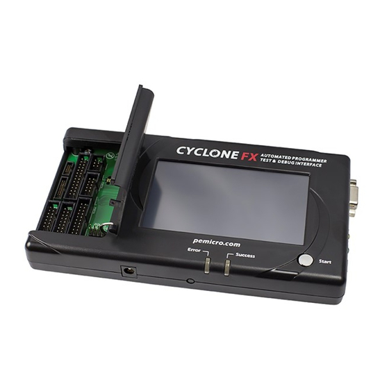
P&E’s line of stand-alone programming solutions. The Cyclone for ARM devices is designed to withstand the demands of a production environment. It is a Stand-Alone Programmer (SAP) that can be operated manually or used to host automated programming. In manual SAP mode the unit is operated using buttons and/or the LCD Menu. - Page 8 Cyclone for ARM devices ® • Executes SAP operations • Selects SAP image • Configures Cyclone for ARM devices IP settings • Displays operation status • Convenient LED Display • Indicates success or failure • Multiple Communication Interfaces • Ethernet 10/100 baseT •...
- Page 9 • Powerful Automated Control Package For Production Control • Basic Automated Control Package (included) supports host- controlled SAP operations for one Cyclone for ARM devices. Professional and Enterprise Automated Control Packages available for purchase. • Multiple Cyclones for ARM devices can create a Gang Programmer using a variety of different communication interfaces.
-
Page 10: Quick Start Guide For Sap Operation
® QUICK START GUIDE FOR SAP OPERATION Stand-Alone Programming (SAP) is the most common use of the Cyclone for ARM devices. This quick start guide illustrates how easy it is to begin using the Cyclone for stand-alone programming. You are encouraged to read this manual in its entirety for a complete description of all Cyclone for ARM devices features, many of which are beyond the scope of this quick-start guide. - Page 11 ® information, programming algorithm, programming sequence, and target data. The Cyclone for ARM devices uses these images to perform SAP operations on target devices. Follow these steps to create a SAP image: a. Run the Cyclone Image Creation Utility This utility is a GUI designed to help users create architecture/ manufacturer-specific SAP images.
- Page 12 Cyclone for ARM devices ® Figure 2-1: Cyclone Image Creation Utility b. Click on Select New Device to open the Device Selection Dialog. Drill down the device tree and select your device. Cyclone for ARM devices User Manual...
- Page 13 The programming algorithm, target object file, and default pro- gramming sequence will then show up in the programming sequence listbox. d. Specify the auxiliary setup and hardware setup, such as Commu- nication Mode, Communication Rate, Target Power, and Voltage Settings. Cyclone for ARM devices User Manual...
- Page 14 Step 4. Execute SAP Image The SAP image stored on your Cyclone for ARM devices can now be executed with one button press. Once your target is connected to the Cyclone for ARM devices, press the “START” button of the Cyclone for ARM devices unit and wait for programming operations to finish.
-
Page 15: Cyclone For Arm Devices Hardware
® CYCLONE FOR ARM DEVICES HARDWARE The following is an overview of the features and interfaces of the Cyclone for ARM devices unit. The interfaces are labeled on the underside of the Cyclone unit. Cyclone for ARM devices Power Supply The Cyclone for ARM devices requires a regulated 6V DC Center Positive power supply with 2.5/5.5mm female plug. -
Page 16: Ethernet Communication
Figure 3-5: Cyclone for ARM devices Ethernet Connector USB Communications The Cyclone for ARM devices provides a USB connector for Universal Serial Bus communications between the Cyclone for ARM devices and the host computer. The Cyclone for ARM devices is a USB 1.1 compliant device. -
Page 17: Electromechanical Relays
P&E only recommends switching DC voltages up to 24 Volts. Power Connectors The Cyclone for ARM devices provides a Target Power Supply Input Jack and a Target Power Supply Output Jack with 2.5/5.5 mm Pin Diameter. The power jacks are connected or disconnected by two electromechanical relays. When connected, the Center Pin of the Target Power Supply Input Jack is connected to the Center Pin of the Target Power Supply Output Jack. -
Page 18: Jumper Settings
Jumper Settings The jumpers must be set differently for various power management options that the Cyclone for ARM devices offers. If the Cyclone for ARM devices is not being used to manage the target’s power, only Jumper 5 needs to be installed. -
Page 19: 20-Pin Debug Connector
Figure 3-9: Mini 10-Pin and Mini 20-Pin Keyed Header Dimensions 20-Pin Debug Connector The Cyclone provides a 20-pin 0.100-inch pitch double row connector for ARM targets. The 20-pin standard connector pin definitions for JTAG mode Cyclone for ARM devices User Manual... - Page 20 GND - PIN 18 PIN 19 - NC GND - PIN 20 The Cyclone for ARM devices also supports SWD Mode. This replaces the JTAG connection with a clock and single bi-directional data pin. 20-Pin Standard Connector SWD Mode Pin Assignments...
- Page 21 Cyclone for ARM devices ® Figure 3-10: Communications Mode Selection The location of the 20-pin standard connector is displayed below. Figure 3-11: 20-Pin Connector Cyclone for ARM devices User Manual...
-
Page 22: 20-Pin Keyed Mini Connector
NC - PIN 18 PIN 19 - GND NC - PIN 20 The Cyclone for ARM also supports SWD Mode. This replaces the JTAG connection with a clock and single bi-directional data pin. 20-Pin Keyed Mini Connector SWD Mode Pin Assignments... - Page 23 Cyclone for ARM devices ® Figure 3-12: Communications Mode Selection The location of the 20-pin keyed mini connector is displayed below. Figure 3-13: 20-Pin Keyed Mini Connector Cyclone for ARM devices User Manual...
-
Page 24: 10-Pin Keyed Mini Connector
TDI - PIN 8 PIN 9 - NC RESET - PIN 10 The Cyclone for ARM also supports SWD Mode. This replaces the JTAG connection with a clock and single bi-directional data pin. 10-Pin Keyed Mini Connector SWD Mode Pin Assignments... - Page 25 Cyclone for ARM devices ® Figure 3-14: Communications Mode Selection The location of the 10-pin keyed mini connector is displayed below. Figure 3-15: 10-Pin Keyed Mini Connector Cyclone for ARM devices User Manual...
-
Page 26: Jtag Daisy Chain
® 3.12 JTAG Daisy Chain The Cyclone for ARM devices supports processors in a JTAG daisy chain configuration. This type of configuration is desirable if the user wants to share a single debug connector across multiple JTAG devices. To start, it is required that the user selects the JTAG communications mode in the Cyclone Image Creation Utility (see Section 5.1 - Create A Stand-Alone... -
Page 27: Ribbon Cable
Cyclone for ARM devices Debug Connector has the same pinout as the Target Header, i.e., Pin 1 of the Cyclone for ARM devices Debug Connector is connected to Pin 1 of the Target Header. Figure 3-17 sketches the connection mechanism (looking down into the sockets) for a 14-pin ribbon cable. -
Page 28: Target Power Management
Each configuration will have an associated jumper setting that MUST be set on the Cyclone for ARM devices. The jumper header is found on the long front side of the unit, directly to the left of the Target Power In and Out jacks. - Page 29 3.14.1 Using Power In Jack and Power Out Jack The target power supply is connected to the Power In Jack of the Cyclone for ARM devices. The Power Out Jack of the Cyclone for ARM devices is connected to the target system via the Power In and Power Out jacks. Figure 3-19 shows the connections.
- Page 30 3.14.2 Using Cyclone for ARM devices Board Power and Power Out Jack The target power supply is not needed. The Power Out Jack of the Cyclone for ARM devices will act as a center positive power supply to the target system.
- Page 31 3.14.3 Using Cyclone for ARM devices Board Power and Debug Connector TVCC The target power supply is not needed. The TVCC pin of the Cyclone for ARM devices’ debug connector provides the appropriate voltage for corresponding ARM targets. The Power Out jack of the Cyclone for ARM devices connector is not needed.
- Page 32 Cyclone for ARM devices ® Figure 3-24: Jumper Settings for Target Power Connection via Cyclone for ARM devices Board Power and TVCC of Cyclone for ARM devices Debug Connector 3.14.4 Using Power IN Jack And Debug Connector TVCC Pin A center positive power supply is connected to the Power IN Jack of the Cyclone for ARM devices.
-
Page 33: Compactflash Port
3.14.5 Target Powered Independently Of Cyclone for ARM devices A target may be powered independently of the Cyclone for ARM devices. The user should remove all jumpers on the Cyclone for ARM devices except jumper 5 if they elect to provide a separate power source for the target. -
Page 34: Cyclone Lcd Menu
Note: These menus change as features are added to the Cyclone for ARM devices, so if your menus do not match those displayed here, please check P&E’s website, www.pemicro.com, for a user manual containing the latest LCD Menu operations information. -
Page 35: Status Window
® Status Window Figure 4-2: Status Window The status window appears when the Cyclone for ARM devices is powered on. This window lists the following information: 1. Firmware version of the Cyclone. 2. IP address assigned to the Cyclone. -
Page 36: Main Menu
Select SAP Image Select SAP Image brings up a display listing the images that are stored in the Cyclone for ARM devices’ memory. You may select the appropriate image by using the Up/Down arrows to highlight it, and then pressing the “Select”... - Page 37 Operation Via LCD Menu. Please refer to that section for additional menu information. 4.2.5 Configure Cyclone Figure 4-5: Configure Cyclone Configure Cyclone brings up a submenu with three options from which to choose. 4.2.5.1 Configure Cyclone: Edit IP Settings Figure 4-6: Configure Cyclone: Edit IP Settings...
- Page 38 Figure 4-7: Edit IP Settings: Edit IP Number Edit IP Settings: Edit IP Mask Edit IP Mask allows the user to set an IP Mask for the Cyclone for ARM devices. The current IP Mask is displayed on the second line.
- Page 39 Edit IP Settings: Edit IP Gateway Edit IP Gateway allows the user to set the IP Gateway for the Cyclone for ARM devices. The current IP Gateway is displayed on the second line. Use the Up/Down buttons to scroll through the characters.
- Page 40 4.2.5.2 Configure Cyclone: Edit Cyclone Name Edit Cyclone Name allows the user to set the name for the Cyclone for ARM devices. The current name is displayed on the second line. Use the Up/Down buttons to scroll through the characters. To select a character, hit the Select button.
- Page 41 Cyclone for ARM devices ® Figure 4-12: Configure Cyclone: Set AUX Button Func Cyclone for ARM devices User Manual...
-
Page 42: Stand-Alone Programmer Configuration
This chapter describes in detail how to configure the Cyclone for ARM devices for stand-alone programming using the Cyclone Image Creation Utility, shown in Figure 5-1. The Cyclone for ARM devices does not require a target to be connected when it is being configured. However, the power of the Cyclone for ARM devices must be turned on (indicated by the “Idle”... - Page 43 ® 5.1.1 Specify your Processor The Cyclone for ARM supports ARM Cortex devices by Freescale, STMicroelectronics, Texas Instruments (TI), NXP, Atmel, Infineon, and Silicon Labs. Click on the Select New Device button to open the Device Selection Dialog. Drill down the device tree to select your device.
- Page 44 To specify the programming algorithm for the target, double-click on the Choose Algorithm (CM) function in the left panel. Or, you may highlight it and add it to the right panel using the arrow (->). This opens the Load Programming Algorithm dialog. Cyclone for ARM devices User Manual...
- Page 45 Specify S-Record (SS) in the left panel. This opens a dialog which allows you to select the appropriate S-Record. Once both the algorithm and S-Record are selected, the full list of programming functions becomes available in the left panel. Cyclone for ARM devices User Manual...
- Page 46 Cyclone for ARM devices ® Figure 5-5: Programming Functions Enabled Next, the user should add additional programming functions to complete the programming script. Cyclone for ARM devices User Manual...
- Page 47 The Remove From List button can be used to remove a selected command from the right panel. At this point the image can be saved to a disk or to the Cyclone for ARM Cyclone for ARM devices User Manual...
- Page 48 This will cause any out of range errors to be ignored. Erase If Not Blank This command performs a blank check of the module and erases it if it is not blank. Erase Module Cyclone for ARM devices User Manual...
- Page 49 Program Serial Number This command becomes available once a programming algorithm is selected. It will instruct the Cyclone for ARM devices to program the serial number to the target once executed. As with other commands, the serial number will not be programmed until the SAP operations are carried out.
- Page 50 The debug connector pin definitions are listed for reference. 5.1.5 Target Voltage and Power Settings A user may elect to use Cyclone for ARM devices to supply power to the target. In this case, the Target Voltage specifies the target MCU I/O voltage level.
- Page 51 USB, or Ethernet interfaces. The Port drop-down list allows the user to select from one of the Cyclones available on that interface. In the case of a Cyclone present on a different network (i.e., not displayed automatically in the Port drop-down list), the user may specify its IP address by using the Specify IP button.
-
Page 52: Manage Multiple Sap Images
Cyclone for ARM devices ® configuration into a file, which may be used for future reference, e.g., comparing the Cyclone for ARM devices contents with the file to see if they are the same. 5.1.11 Load Cyclone Configuration “Load Cyclone Configuration” in the file menu allows the user to load a configuration that has previously been saved in order to create a new image. - Page 53 ® Figure 5-9: Manage Images Utility Upon opening a selected Cyclone for ARM devices, the user is provided in the top left panel with a list of the images currently on the unit’s internal memory. If the CompactFlash license has been activated, a list of images on any connected CompactFlash card will also be displayed in the bottom left panel.
- Page 54 Cyclone for ARM devices ® are made to the Cyclone for ARM devices until the “Commit Changes” button is pressed. Note: Any images that are already stored on the Cyclone for ARM devices or CompactFlash can only be removed by using the corresponding “Remove All Images...”...
-
Page 55: Stand-Alone Programmer Manual Control
Operation Via Cyclone for ARM devices Buttons There are five (5) buttons on the top of the Cyclone for ARM devices which are used for stand-alone programming and to navigate the LCD menus. They are specified as follows. - Page 56 6.1.3 Example When the Cyclone for ARM devices is powered up, the Idle LED is turned on. After the user programs the contents and procedures into the Cyclone for ARM devices on-board flash, the Cyclone for ARM devices may be used as a Stand-Alone Programmer.
-
Page 57: Operation Via Lcd Menu
® Operation Via LCD Menu The Cyclone for ARM devices may be operated by making selections from the LCD menu. This section describes the layout of the menus and the functions that each may be used to perform. Figure 6-1: LCD Menu Overview... - Page 58 ® 6.2.1 Status Window Figure 6-2: Status Window The status window appears when the Cyclone for ARM devices is powered on. This window lists the following information: 1. Firmware version of the Cyclone. 2. IP address assigned to the Cyclone.
- Page 59 The Main Menu is accessible by pressing the “Menu” button when the status window is displayed. The Main Menu contains four selections. This section contains information on Execute SAP Function and Show Statistics. For information on Select SAP Image and Configure Cyclone, please refer to CHAPTER 4 - CYCLONE LCD MENU. 6.2.2.1...
-
Page 60: Cyclone Battery Pack
6.2.2.3 Show Statistics The fourth line (PCIP:) displays the IP address of the last PC to control the Cyclone for ARM devices. The other categories listed are for future use and are not currently implemented. Figure 6-6: Show Statistics Cyclone Battery Pack Manual control of stand-alone mode is also useful for performing field updates. - Page 61 ® Figure 6-7: Cyclone with Cyclone PowerPack The combination of the Cyclone for ARM devices programmer and the battery pack creates a fully operational field programming setup that is lightweight, compact, and extremely portable. All that is required for a field update is to connect the battery-powered, pre-programmed Cyclone to the target and initiate programming.
-
Page 62: Stand-Alone Programmer Automated Control
The .DLL in the Basic Edition allows custom software applications to control one Cyclone unit. Users wishing to use a .DLL to control more than one Cyclone or who would prefer to use RS232/Ethernet protocols (e.g., in a non-Windows environment) may purchase the appropriate advanced version of the Cyclone Automated Control Package. -
Page 63: Cyclone Automated Control Package - Details
7.2.2 .DLL Control The dynamic link library (DLL) that is included in all editions of the Cyclone Automated Control Package allows you to create an application on the PC that can directly control one (Basic Edition) or more P&E Cyclone units. - Page 64 Enterprise Edition of the Cyclone Automated Control Package allow a developer to manually send individual command packets to control each Cyclone unit. This is ideal for setups that do not have access to a PC or production environments that do not run Windows-based computers.
-
Page 65: Ethernet Configuration
® ETHERNET CONFIGURATION This section describes the mechanism used by the Cyclone for ARM devices device to transact data over an Ethernet network. It primarily focuses on the User Datagram Protocol (UDP), which is a popular method for sending data over a network when the speed of a data transaction is of more concern than the guarantee of its delivery. -
Page 66: Network Parameters
Before first use, the Cyclone needs to be programmed with a unique IP number, the Subnet Mask IP number, and also the default Gateway’s IP number. This can be done via the USB or the Serial port, and is described in... -
Page 67: Internet Protocol
PC with an Ethernet cable. The most basic method is to connect the Cyclone directly to a PC, via a cross-over Ethernet cable. However, the more common method is to place the Cyclone and the PC on the same network Cyclone for ARM devices User Manual... - Page 68 8.4.2 Connecting Cyclone-to-PC via an Ethernet cable In order to connect the Cyclone to a PC directly via an Ethernet cable, you need to use what is known as a cross-over cable. A cross-over cable, which is Cyclone for ARM devices User Manual...
-
Page 69: Cyclone Ip Setup Via Lcd Menu
With this configuration, it is still important to assign IP numbers to both the PC and the Cyclone device. Although at first glance it may not seem necessary to assign a Gateway address in this configuration, the Cyclone was designed to operate on a network of more than two computers, and therefore it needs to be programmed with a Gateway address. - Page 70 (2) Drop-down Box 2 Once one of the three (Serial, USB, or Ethernet) communication interfaces has been selected in the first drop-down box, a list of all available Cyclone devices over that interface will be displayed for selection. (3) Close Button The “Close”...
- Page 71 It needs to be a unique IP number which can be accessible on the network. (7) Cyclone Device Name This is a label which can be used to identify the Cyclone for ARM devices by name, e.g., “John’s Cyclone” or “Manufacturing Floor.” (8) MAC Address This is the Media Access Control address, the unique number of an Ethernet device on the network.
-
Page 72: Using Configureip.exe To Configure The Cyclone For Arm Devices
Cyclone for ARM devices software distribution. In order to update the network parameters, perform the following steps: 1. Connect a Cyclone for ARM devices to the PC via a serial or a USB cable, and make sure that it is powered before launching the Cyclone Configuration Utility. - Page 73 ® Figure 8-3: Cyclone IP Setup Utility - Continue Setup 3. The Cyclone for ARM devices now needs to be programmed with IP numbers for the network on which it will operate. The Cyclone IP Number field must contain a unique IP number.
-
Page 74: Serial Port Configuration
Cyclone for ARM devices ® SERIAL PORT CONFIGURATION Standard serial cables may be used for serial port Cyclone for ARM devices configuration. Cyclone for ARM devices User Manual... -
Page 75: Usb Port Configuration
Cyclone for ARM devices ® USB PORT CONFIGURATION Standard USB cables may be used for USB port Cyclone for ARM devices configuration.The user may use network hubs as necessary. Cyclone for ARM devices User Manual... -
Page 76: Automatic Serial Number Mechanism
In addition, the serial number is incremented to the next available serial number and saved for future serialized programming operations. The Cyclone for ARM devices adopts this automatic serial number mechanism for its stand-alone operations. 11.1... -
Page 77: Serialize Utility
"None Selected". If the file exists, the serial number and its properties are displayed on screen. • Double Click or …Click - Opens a standard file browser and lets you Cyclone for ARM devices User Manual... - Page 78 Up Arrow Click - Increases the upper bound by one with a maximum of FF Hex. • Down Arrow Click - Decreases the upper bound by one with a minimum of the current serial number byte value. Cyclone for ARM devices User Manual...
- Page 79 Serialize.ini. This file will initialize the setup information the next time the program is started. Xing out of the program (top right of screen) does not save the setup info. 11.2.11 BINARY, NUMERIC, CONSTANT, ALPHA UPPER, ALPHA LOWER, and Cyclone for ARM devices User Manual...
-
Page 80: Serialize Utility Example
“PS Program Serial Number”. P&E’s command line software uses the same commands in a command line fashion to invoke the serial number file, initiate its programming, and increment: CS serial_number_file.ser Cyclone for ARM devices User Manual... -
Page 81: Serial Number Handling In Cyclone For Arm Devices
Cyclone for ARM devices’ flash for internal images (or external CompactFlash for external SAP images). The CS and PS commands are not present in the Cyclone Image Creation Utility until a valid programming algorithm is specified. To complement the Cyclone’s usage in production environments, the Cyclone for ARM devices supports multiple serial number structures for each programming algorithm block. - Page 82 Cyclone for ARM devices ® CS serial_file4.ser CS serial_file5.ser Cyclone for ARM devices User Manual...
-
Page 83: Cyclone Error Codes
$000A: Error writing a block of data to target $000B: Error enabling or disabling module $000C: Error in performing timing test $000D: MON08 target had an invalid reset $000E: The selected target processor is not supported by the Cyclone for ARM devices 12.2 SAP Image Handling Errors... -
Page 84: Sap Communication Handling Errors
$2001: Erase error, algorithm not supported $2002: Erase error, algorithm not found $2003: Erase error, module failed or canceled $2004: Erase error, module failed, target is still secured $2005: Erase error, module not performed, data is preserved Cyclone for ARM devices User Manual... -
Page 85: Sap Program Byte, Word, And Module Errors
$4012: VV failed, invalid algorithm $4013: VV operation failed or canceled 12.10 SAP Verify Range and Module Errors $5003: Verification operation failed or canceled 12.11 SAP User Function Errors $6003: User function failed or canceled Cyclone for ARM devices User Manual... -
Page 86: Sap Trim Errors
$800F: Fatal Error, please contact P&E $8010: Fatal Error, please contact P&E $8011: Fatal Error, please contact P&E $8012: Fatal Error, please contact P&E $8013: Fatal Error, please contact P&E $8014: Fatal Error, please contact P&E Cyclone for ARM devices User Manual... -
Page 87: External Memory Errors
$B003: Total number of Serial Number Structures is over limit of 254. $B004: Error converting serial number structure $B005: Error updating serial number $B006: Serial number structure not found $B007: Serial number structure invalid Cyclone for ARM devices User Manual... -
Page 88: Successful Download Counter Errors
$C003: Total number of download counter is over limit of 254. $C004: Error converting download counter structure 12.17 System Hardware/Firmware/Logic Recoverable Errors $D001: Firmware does not exist $D002: Firmware update not allowed $D003: Firmware update failed $D004: Firmware update mismatch Cyclone for ARM devices User Manual...
Need help?
Do you have a question about the CYCLONE and is the answer not in the manual?
Questions and answers