PE micro Cyclone MAX User Manual
Hide thumbs
Also See for Cyclone MAX:
- Developer's manual (61 pages) ,
- Getting started manual (8 pages) ,
- User manual (88 pages)
Table of Contents
Advertisement
Quick Links
Advertisement
Table of Contents

Related Manuals for PE micro Cyclone MAX


Summary of Contents for PE micro Cyclone MAX
- Page 2 Purchase Agreement P&E Microcomputer Systems, Inc. reserves the right to make changes without further notice to any products herein to improve reliability, function, or design. P&E Microcomputer Systems, Inc. does not assume any liability arising out of the application or use of any product or circuit described herein. This software and accompanying documentation are protected by United States Copyright law and also by International Treaty provisions.
-
Page 3: Table Of Contents
CYCLONE PRO INTRODUCTION .................... 1 GETTING STARTED ..................3 Software Installation ..................3 Overview Of Cyclone MAX Configuration Utility..........3 CYCLONE MAX HARDWARE ................ 6 Power Source ....................6 Serial (RS232) Communications Port ............6 USB 1.1 Communications Port............... 7 Ethernet Communications Port ..............7... - Page 4 Connecting the Cyclone Device ..............67 Cyclone IP Setup Via LCD Menu ..............69 Cyclone IP Setup Utility User Interface (ConfigureIP) ........69 Using IPSetup.exe to configure the Cyclone Max ........71 Managing Multiple Images ................73 SERIAL PORT CONFIGURATION ............... 75 USB PORT CONFIGURATION ..............76...
-
Page 5: Introduction
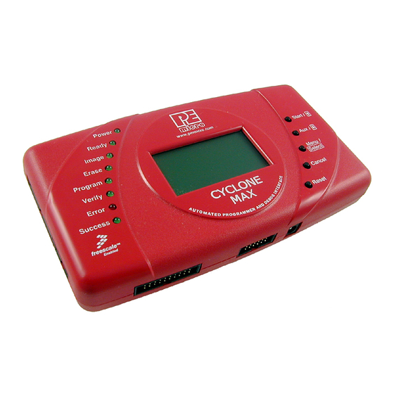
CYCLONE MAX INTRODUCTION The Cyclone MAX is a versatile tool that can be used for the programming, debugging, and testing of microprocessor-based hardware. It can be controlled interactively via a Host PC, or operate independently of the PC in stand-alone mode. The Cyclone MAX can also be configured and operated via Serial, USB, and Ethernet communication interfaces. - Page 6 5 Volts. • LCD Menu • Allows simple, menu-based control of the configuration and function of the Cyclone MAX. In short, the Cyclone MAX is an all-in-one solution for debugging, programming, and testing of your hardware. Cyclone MAX User Manual...
-
Page 7: Getting Started
If you plan to use the Serial or USB ports for communication, then the Cyclone MAX can be used right out of the box. If you wish to use the Ethernet port, however, you will need to configure the corresponding IP numbers before use. - Page 8 (1) Provides a list of available functions that the user may select and add to the programming sequence. (2) This window is where the programming steps are sequenced. (3) This button moves selected programming functions into the sequence window. (4) Displays the processor architecture and the corresponding interface Cyclone MAX User Manual...
- Page 9 The complete functionality of the Cyclone MAX and its accompanying utilities is beyond the scope of this Getting Started section. Please read further to learn more about the full feature set and operation of the Cyclone MAX. For a detailed description of the Cyclone MAX Configuration Utility, please refer to Section 4 - STAND-ALONE PROGRAMMER CONFIGURATION .
-
Page 10: Cyclone Max Hardware
CYCLONE MAX CYCLONE MAX HARDWARE This section describes the various ports and inputs of the Cyclone MAX. Power Source The Cyclone MAX requires a regulated 6V DC Center Positive power supply with 2.5/5.5mm female plug. The Cyclone MAX receives its power from the power jack located on the side of the unit. -
Page 11: Usb 1.1 Communications Port
CYCLONE MAX USB 1.1 Communications Port The Cyclone MAX provides a USB connector for communicating with a PC via the Universal Serial Bus port. The Cyclone MAX is a USB 1.1 compliant device. Figure 3-3: USB Port Ethernet Communications Port The Cyclone MAX provides a standard RJ45 socket for communication with a host computer through the Ethernet Port. -
Page 12: Port A - Coldfire V1 Core
For the physical dimensions of the connector, please see Section 3.14 - Ribbon Cable with IDC Socket. Figure 3-5: Port A ColdFire V1 Core Pinout BKGD 1 2 GND NC 3 4 RESET NC 5 6 VDD Cyclone MAX User Manual... -
Page 13: Port B - Powerpc Nexus Interface
VDDE7 JCOMP 3.6.1 BERG14-to-MICTOR38 Optional Connector (PORT B) P&E offers a 14-pin BERG to 38-pin MICTOR adapter, sold separately, that may be used on Port B of the Cyclone MAX. The P&E part number is BERG14-TO-MICTOR38. Cyclone MAX User Manual... - Page 14 CYCLONE MAX Figure 3-7: BERG14-TO-MICTOR38 Adapter (Sold Separately) Cyclone MAX User Manual...
-
Page 15: Port C - Coldfire Interface & Coldfire Extension Cable
ColdFire extension cable (for synchronous ColdFire targets) or a standard 26- pin ribbon cable (for asynchronous ColdFire targets). Both cables are provided in the Cyclone MAX package. Please refer to each processor’ s user manual to identify whether it is a synchronous or asynchronous interface. If you are not sure, or for test purposes, the synchronous cable will work with all 52xx, 53xx, and 54xx targets. - Page 16 DSCLK RESET PST3 PST2 PST1 PST0 DDATA3 DDATA2 DDATA1 DDATA0 The ColdFire extension cables, one for Synchronous targets and one for Asynchronous targets, are pictured below: Figure 3-9: ColdFire Extension Cable With Adapter (Synchronous ColdFire Targets) Cyclone MAX User Manual...
- Page 17 CYCLONE MAX Figure 3-10: ColdFire Ribbon Cable (Asynchronous ColdFire Targets) Cyclone MAX User Manual...
-
Page 18: Port D - Powerpc Interface
Port D can be used to connect to PowerPC BDM (5xx/8xx) targets. For the physical dimensions of the connector, please see Section 3.14 - Ribbon Cable with IDC Socket. Figure 3-11: Port D - PowerPC Interface PowerPC Pinout SRESET# DSCLK HRESET# DSDI DSDO Cyclone MAX User Manual... -
Page 19: Port E - Arm Nexus
Section 3.14 - Ribbon Cable with IDC Socket. Figure 3-12: Port E- ARM Nexus ARM Nexus Pinout TVCC TRST# 11 12 13 14 RESET# 15 16 17 18 19 20 Cyclone MAX User Manual... -
Page 20: Port F - Reserved
Port F is reserved for future use by P&E. Do not connect to this port. Figure 3-13: Port F 3.11 Expansion Port (CompactFlash) The CompactFlash Port is for future use by P&E. Do not use this port. Figure 3-14: CompactFlash Port (Unimplemented) Cyclone MAX User Manual... -
Page 21: Cyclone Max Buttons
CYCLONE MAX 3.12 Cyclone MAX Buttons There are five (5) buttons on the top of the Cyclone MAX which are used for stand-alone programming and to navigate the LCD menus. They are specified as follows. Button Function START / Start executing the tasks pre-configured into the Cyclone MAX. - Page 22 The ribbon cables are designed such that the Cyclone MAX Ports and target BDM Ports must have the same pinout, i.e., Pin 1 of a Cyclone MAX Port is connected to Pin 1 of the target BDM header. Here is an example...
- Page 23 N/C signifies a No Connect. This pertains to pins that are reserved for future use by Freescale or P&E Microcomputer Systems, and should not be connected. • A signal name ending in # (e.g. RESET#) signifies an active-low signal. Cyclone MAX User Manual...
-
Page 24: Stand-Alone Programmer Configuration
ARM MAC7xxx targets. A simple user interface, CreateImage.exe, is provided for configuring the Cyclone MAX. The Cyclone MAX does not require a target to be connected when it is being configured. However, the Cyclone MAX must be powered on (indicated by the “... -
Page 25: Target Architectures
CYCLONE MAX Target Architectures The Cyclone MAX supports the PowerPC MPC5xx/8xx, PowerPC Nexus MPC55xx, ColdFire MCF5xxx, and ARM MAC7xxx architectures. The user may select the target architecture by clicking the corresponding tab. Alternately, the user may select the target architecture through the File menu. - Page 26 4.1.1 PowerPC MPC5xx/8xx The user may configure the Cyclone MAX to operate on a PowerPC MPC5xx/ 8xx target by switching to the PowerPC option in the drop-down list. Alternately, the user may select the PowerPC target through the File menu.
- Page 27 4.1.2 ColdFire MCF5xxx The user may configure the Cyclone MAX to operate on a ColdFire MCF5xxx target by switching to the ColdFire MCF5xxx option in the drop-down list. Alternately, the user may select the ColdFire MCF5xxx target through the File menu.
- Page 28 4.1.3 ARM MAC7xxx The user may configure the Cyclone MAX to operate on an ARM MAC7xxx target by switching to the ARM option in the drop-down list. Alternately, the user may select the ARM MAC7xxx target through the File menu.
- Page 29 4.1.4 PowerPC Nexus The user may configure the Cyclone MAX to operate on a PowerPC Nexus target by switching to the PowerPC Nexus option in the drop-down list. Alternately, the user may select the PowerPC Nexus target through the File menu.
-
Page 30: Bdm Shift Clock Delay Constant
The BDM Shift Clock Delay Constant allows the user to set the BDM shift clock speed of the Cyclone MAX. The equation for determining the shifting frequency is: 50000000 / (5 + 2*n). This clock cannot generally exceed a div 6 of the processor bus frequency. - Page 31 For example, in Figure 4-8, three programming functions have been selected and sequenced by the Script Wizard. Cyclone MAX User Manual...
- Page 32 CYCLONE MAX Figure 4-8: Script Wizard Dialog - Programming Functions Selected Upon completion, click OK and the script information will appear in the Specify Programming Script dialog. Figure 4-9: Results Of Script Wizard Dialog Cyclone MAX User Manual...
-
Page 33: Programming Operations
This command performs a blank check of the module and erases it if it is not blank. Erase Module If “ Erase Module” is specified, the Cyclone MAX will perform an “ Erase Module” on the target device after entering the Monitor Mode or BDM mode. Cyclone MAX User Manual... -
Page 34: Store Image To Cyclone
CYCLONE MAX Blank Check Module If “ Blank Check Module” is checked, the Cyclone MAX will perform a “ Blank Check Module” on the target device. Program Bytes Prompts for a starting address, which must be in the module. You are then asked to enter a hexadecimal byte to be programmed into the current location. -
Page 35: Save Image/Cyclone Configuration
“ Save Cyclone Configuration,” in the file menu, allows the user to save the configuration into a file, which may be used for future reference, e.g., comparing the Cyclone MAX contents with the file to see if they are the same. Configuration Via LCD Menu The following section describes configuration of the Cyclone MAX using the LCD menus. - Page 36 Figure 4-12: Overview Of Cyclone Menu Structure 4.9.1 Status Window Figure 4-13: Status Window The status window appears when the Cyclone MAX is powered on. This lists the following information: 1. The firmware version of the MAX. 2. The IP address assigned to the MAX.
- Page 37 5. The number of programming images in the MAX’ s memory. 6. The name of the selected programming image. 7. Current status. 8. Results of the last operation performed. Hit the MENU/[SELECT] button on the Cyclone MAX to enter LCD menu mode. 4.9.2 Main Menu...
- Page 38 Operation Procedure via LCD Menu. Please refer to that section for additional menu information. 4.9.2.4 Configure Cyclone Figure 4-16: Configure Cyclone Configure Cyclone brings up a submenu with three options from which to choose. Selecting Edit IP Settings brings up a submenu with four options: Cyclone MAX User Manual...
- Page 39 Edit IP Settings: Edit IP Number Edit IP Number allows the user to set an IP number for the Cyclone MAX. The current IP number is displayed on the second line. Use the Up/Down buttons to scroll through the characters. To select a character, hit the Select button. When you are finished, scroll through the characters until you reach the ->...
- Page 40 Edit IP Settings: Edit IP Gateway Edit IP Gateway allows the user to set the IP Gateway for the Cyclone MAX. The current IP Gateway is displayed on the second line. Use the Up/Down buttons to scroll through the characters. To select a character, hit the Select button. When you are finished, scroll through the characters until you reach the ->...
- Page 41 Configure Cyclone: Set AUX Button Func Set AUX Button Func allows the user to assign a function to the AUX button of the Cyclone MAX. If more than one choice is available, highlight the function that you wish to assign to the AUX button and...
- Page 42 CYCLONE MAX press the Select button to choose it. Figure 4-23: Configure Cyclone: Set AUX Button Func Cyclone MAX User Manual...
-
Page 43: Stand-Alone Programmer Manual Control
The target power management schemes remain the same for each control method. Via Cyclone MAX Buttons There are five (5) buttons on the top of the Cyclone MAX which are used for stand-alone programming and to navigate the LCD menus. They are specified as follows. -
Page 44: Operation Procedure Via Lcd Menu
8. Success – Programming functions completed successfully Operation Procedure via LCD Menu Rev. B of the Cyclone MAX may be operated by making selections from the LCD menu. This section describes the layout of the menus and the functions that each may be used to perform. - Page 45 CYCLONE MAX 5.2.1 Status Window Figure 5-2: Status Window The status window appears when the Cyclone MAX is powered on. This lists the following information: 1. The firmware version of the MAX. 2. The IP address assigned to the MAX.
- Page 46 5.2.2.2 Show Statistics The fourth line (PCIP:) displays the IP address of the last PC to control the Cyclone MAX. The other categories listed are for future use and are not currently implemented. Figure 5-5: Show Statistics Cyclone MAX User Manual...
-
Page 47: Stand Alone Programmer Automated Control
MAX. 6.1.1 Startup a) Connect the Cyclone MAX to the PC via Serial Port, USB Port, or Ethernet. b) Connect the Cyclone MAX to the target system. c) Power up the PC and the target system. d) Run the software from the DOS prompt. Allowed command-line... - Page 48 Start the first programming image on the Cyclone which is connected to USB1 port. CYCLONEMAX_LAUNCH Port=209.61.110.251 Cyclone MAX is connected to a network with IP address of 209.61.110.251 CYCLONEMAX_LAUNCH Port=209.61.110.251 Image=3 Start the third programming image on the Cyclone which is connected to the network with the IP address of 209.61.110.251.
- Page 49 CYCLONE MAX available, and the USB cable is connected. 193: Specified Ethernet IP address is incorrect. 199: The Cyclone MAX device is not ready. Please check power and connections. Execution related error codes: $0001: Unable to detect target communication speed.
-
Page 50: Automated .Dll Control Of The Cyclone
Windows .DLL. The .DLL allows a host application to connect to a Cyclone unit via Ethernet and control stand-alone programming operations. Included with the Cyclone MAX is a .DLL which allows control of a Cyclone unit. Example code and documentation is included which demonstrates use of... - Page 51 6.2.1 Connecting/Disconnecting from the Cyclone In order to control a Cyclone PRO or Cyclone MAX unit from a host computer, the host computer must initiate a connection to a Cyclone unit. The connect_to_cyclonepromax_by_ip call opens a connection to the Cyclone unit via Ethernet.
- Page 52 *port_identifier); Description: This function opens a session with a Cyclone PRO or Cyclone MAX by its IP address. The port_identifier parameter is a pointer to a null-terminated character string in the format xxx.xxx.xxx.xxx, where xxx = 0..255. The return value is the handle to the open Cyclone PRO or Cyclone MAX, which must be passed to other routines as a parameter.
- Page 53 Figure 6-7: Call Sequence Detail 6.2.2.1 Call: START_execute_all_commands C/C++ Prototype: bool START_execute_all_commands(unsigned long cyclonepromaxhandle, unsigned long imagenumber); Description: A Cyclone unit may have several independent programming images in non- volatile memory. A programming image contains the programming algorithms, Cyclone MAX User Manual...
- Page 54 Call: check_STARTED_cyclonepromax_status C/C++ Prototype: unsigned int check_STARTED_cyclonepromax_status(unsigned long cyclonepromaxhandle); Description: Checks to see if the Cyclone PRO or Cyclone MAX has completed a programming operation started with either the START_execute_all_commands or START_dynamic_program_bytes routines. The results are: 1 = Currently Programming...
- Page 55 6.2.2.4 Call: get_last_error_code C/C++ Prototype: unsigned short get_last_error_code(unsigned long cyclonepromaxhandle); Description: Returns the last error code of the Cyclone PRO or Cyclone MAX. 0 = No Error. 6.2.2.5 Call: get_last_error_addr C/C++ Prototype: unsigned int get_last_error_addr(unsigned long cyclonepromaxhandle);...
- Page 56 A “ true” result indicates that the images are the same. The aFile pointer should point to a null terminated filename, which is the full pathname of the file. Cyclone MAX User Manual...
- Page 57 “ 0” if the operation failed. 6.2.3.6 Call: toggle_power_no_background_entrance C/C++ Prototype: bool toggle_power_no_background_entrance(unsigned long cyclonepromaxhandle); Description: Causes the RESET line of the target processor to be driven low, then pulled up high to enter normal operation mode. Cyclone MAX User Manual...
- Page 58 Just open the project/workspace in your compiler and you will be able to build the sample application without any modifications. Figure 6-8: Cyclone PRO/MAX Control Utility Example The sample applications come pre-compiled with ICONS, so you can run Cyclone MAX User Manual...
-
Page 59: Control Of Multiple Cyclone Units
Figure 6-9: Multiple Cyclone PRO/MAX Control Utility Example However, it may also be desirable to control multiple Cyclone units simultaneously from a host PC. Since the Cyclone is a self-contained computer system, including all programming algorithms, data, and processing Cyclone MAX User Manual... - Page 60 This SDK (software development kit) supports both the Cyclone PRO and the Cyclone MAX programmers, meaning that any supported Freescale devices can be programmed in parallel, even if they are different devices with different data. More information may be found at www.pemicro.com.
-
Page 61: Pc-Hosted Debug/Programming Software
5.7 and above) will now have the capability to interface to target hardware using the Cyclone Max. In order to configure CodeWarrior to do so, the user can select the Preferences option from the Edit menu. This brings up the... - Page 62 The image above displays the configuration settings for the Ethernet port of the Cyclone Max. The user can set the IP number, and the BDM Frequency Speed to interface to the target. The higher this value is, the slower the BDM Frequency will be, and it is recommended that for slower targets a higher value be selected.
- Page 63 The image above displays the configuration settings for the USB port of the Cyclone Max. The user can select one of multiple Cyclone devices which are connected to the PC, in case more than one Cyclone Max is attached via the USB port.
- Page 64 7.1.2 CodeWarrior Hardware Diagnostics If the user wishes to test the Cyclone Max connected to their PC, they can use the Hardware Diagnostics selection from the Tools menu. This allows the user to run hardware diagnostics and memory tests to ensure proper operation of all devices.
-
Page 65: P&E Microcomputer Systems' Software
P&E Microcomputer Systems’ Software 7.2.1 In-Circuit Debugger The ICD In-Circuit Debugger uses the Cyclone MAX to control the target devices. Separate ICD software is required for each of the PowerPC 5xx/8xx, ColdFire MPC5xxx, or ARM MAC7xxx architectures. With the ICD In-Circuit... - Page 66 Full source-level debugging 7.2.2 In-Circuit Programmer The PROG In-Circuit Programmer is a general-purpose programmer which allows the user to program a PowerPC 5xx/8xx, ColdFire MPC5xxx, or ARM MAC71xxx device with on-chip EEPROM/FLASH, either from an object file Cyclone MAX User Manual...
- Page 67 P&E’ s PROG software. Please refer to CPROG documentation for more information. 7.2.3 P&E Microcomputer Systems PKG Software Packages P&E’ s software packages contain the WinIDE integrated development environment, which pulls together an assembler, in-circuit simulator, flash memory programmer, and in-circuit debugger. Cyclone MAX User Manual...
- Page 68 CYCLONE MAX 7.2.4 Latest Updates - P&E Software The most recent updates of P&E’ s software products can be requested, after a brief registration, at: http://www.pemicro.com/SRS/main_screen_user.cfm. Cyclone MAX User Manual...
-
Page 69: Ethernet Port Configuration
CYCLONE MAX ETHERNET PORT CONFIGURATION This chapter describes the mechanism used by the Cyclone MAX device to transact data over an Ethernet network. It primarily focuses on the User Datagram Protocol (UDP), which is a popular method for sending data over a network when the speed of a data transaction is of more concern than the guarantee of its delivery. -
Page 70: Network Parameters
This can be done via the USB or the Serial port, and is described in greater detail in Section 8.7 - Using IPSetup.exe to configure the Cyclone Max to configure the Cyclone Max” section of this manual. Internet Protocol... -
Page 71: Connecting The Cyclone Device
PCs through a Hub to one or more Cyclones. In order to connect these devices to the Hub, you will need to use the provided straight-through Ethernet cable. The straight-through cable, which is the “ standard” Ethernet Cyclone MAX User Manual... - Page 72 Cyclone device. Although at first glance it may not seem necessary to assign a Gateway address in this configuration, the Cyclone was designed to operate on a network of more than two computers, and therefore it needs to be programmed with a Gateway address. Cyclone MAX User Manual...
-
Page 73: Cyclone Ip Setup Via Lcd Menu
192.168.100.1 255.255.255.0 Cyclone IP Setup Via LCD Menu For instructions on how to configure the Cyclone MAX using the LCD Menu, please see Section 5.2 - Operation Procedure via LCD Menu. Cyclone IP Setup Utility User Interface (ConfigureIP) Before the Cyclone device transacts data on an Ethernet network, it will need to be configured with the relevant network parameters. - Page 74 IP number which can be accessible on the network. (7) Cyclone Device Name This is a label which can be used to identify the Cyclone MAX by name, e.g., “ John’ s Cyclone” or “ Manufacturing Floor.”...
-
Page 75: Using Ipsetup.exe To Configure The Cyclone Max
In order to update the network parameters, perform the following steps: 1. Connect a Cyclone MAX to the PC via a serial or a USB cable, and make sure that it is powered before launching the Cyclone Configuration Utility. The Cyclone Max Configuration Utility starts... - Page 76 CYCLONE MAX Figure 8-2: Cyclone IP Setup Utility - Initial Screen 2. Assuming that the Cyclone Max is connected to the COM1 serial port of the PC, switch from “ Ethernet Port” to “ Serial Port” , at which point the second drop-down box will display COM1.
-
Page 77: Managing Multiple Images
CYCLONE MAX Figure 8-3: Cyclone IP Setup Utility - Continue Setup 3. The Cyclone Max now needs to be programmed with IP numbers for the network on which it will operate. The Cyclone IP Number field must contain a unique IP number. - Page 78 CYCLONE MAX Figure 8-4: Manage Images Utility (Default Screen) Upon opening a selected Cyclone MAX, the user is provided with a list of the images currently on the unit. This is displayed in the panel to the left, with greyed-out text indicating the current state of the Cyclone MAX. The panel to the right can be used to add or delete additional images.
-
Page 79: Serial Port Configuration
Serial Port. It should be noted that some terminal programs, such as the HyperTerm program are not designed to function with the Cyclone Max. The Cyclone Max operates at a fixed baud rate of 115200 Baud, 8 Data bits, No Parity, and 1 Stop Bit. -
Page 80: Usb Port Configuration
CYCLONE MAX USB PORT CONFIGURATION The Cyclone Max can be connected to the USB port of a PC, or to a USB HUB through a standard USB cable. Cyclone Max supports USB 1.1. Cyclone MAX User Manual...
Need help?
Do you have a question about the Cyclone MAX and is the answer not in the manual?
Questions and answers