Advertisement
Quick Links
Advertisement

Subscribe to Our Youtube Channel
Related Manuals for AC Infinity CLOUDLINE AC-FKS4


Summary of Contents for AC Infinity CLOUDLINE AC-FKS4
- Page 1 CLOUDLINE AIR FILTRATION SYSTEM USER MANUAL USER MANUAL...
- Page 3 WELCOME Thank you for choosing AC Infinity. We are committed to product quality and friendly customer service. If you have any questions or suggestions, please don’t hesitate to contact us. Visit www.acinfinity.com and click contact for our contact information. EMAIL LOCATION support@acinfinity.com...
- Page 4 MANUAL CODE CL2105X1 PRODUCT MODEL UPC-A Air Filtration System 4 AC-FKS4 819137022065 Air Filtration System 6 AC-FKS6 819137021891 Air Filtration System 8 AC-FKS8 819137022072...
-
Page 5: Manual Index
Installation (Filter & Ducting) ............Page 20 Powering and Setup ..............Page 25 Controller Upgrade ................ Page 26 Cleaning ..................Page 27 Programming ................. Page 29 ....................Page 30 Other AC Infinity Products ............. Page 32 Warranty ..................Page 33... -
Page 6: Key Features
KEY FEATURES DUAL BALL BEARINGS ACTIVATED CARBON SPEED CONTROLLER The motor contains ball Features RC412 1200+ IAV Single button controller bearings with a 67,000 hour Australian charcoal with high with circular dot display that lifespan. Enables the fan to be adsorption rate to completely enables fan speed control in mounted in any orientation. -
Page 7: Product Contents
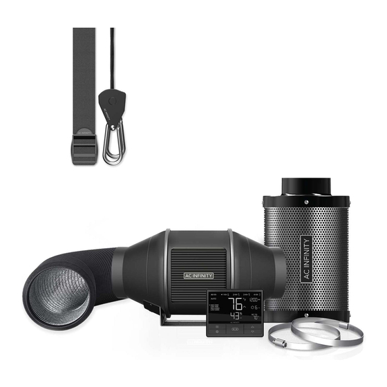
PRODUCT CONTENTS DUCT FAN FLEXIBLE CARBON PREFILTER SYSTEM (x1) DUCTING (x1) FILTER (x1) CLOTH (x2) SPEED TYPE-C DUCT DUCT FAN ROPE CONTROLLER (x1) ADAPTER (x1) CLAMP (x2) SCREW SET (x4) CLIP (x2) FILTER WIRE PROBE WOOD SCREWS STRAPS (x2) MOUNT (x6) MOUNT (x1) - Page 8 PRODUCT CONTENTS...
-
Page 9: Installation
INSTALLATION HANGING INTAKE AND EXHAUST This fan can be used as either an intake fan or an exhaust fan in grow rooms and larger grow tents. To achieve optimal whole space ventilation, the intake fan or opening - if not using a fan - must be situated at a bottom corner of your grow space. - Page 10 INSTALLATION HANGING - ROPE CLIPS Hanging Upward Loop the two rope hangers around a pole and clip the carabiners onto each other. Shorten the loops as needed. Hang the fan by the duct flanges to secure it. Hanging Downward Loop the two rope hangers around a pole and the fan's bracket.
- Page 11 INSTALLATION HANGING - STRAPS STEP 1 Loop the strap around the bracket and a pole. STEP 2 Slip the strap through the inner ladder lock slot from the bottom.
- Page 12 INSTALLATION HANGING - STRAPS STEP 3 Route the strap into the outer ladder lock slot from the top. Adjust the length of the completed loop as needed. STEP 4 Tuck the loose end through the center gap of the ladder lock to secure the loop.
- Page 13 INSTALLATION HANGING - STRAPS STEP 5(a) - Hanging Downward Let the fan hang by the pole once the straps are secure. Make sure the fan's airflow arrow is pointing towards your desired direction. STEP 5(b) - Hanging Upward To hang the fan right-side up, loop and tighten the straps, as shown in steps 1-4, around the pole.
- Page 14 INSTALLATION MOTOR CAP STEP 1 When hanging the fan downwards, the motor cap will appear upside down. You may rotate this motor cap so that it appears right side up. Unscrew the motor cap using a screwdriver. STEP 2 Rotate the motor cap to your desired orientation.
- Page 15 INSTALLATION MOUNTING STEP 1 Unscrew the bolts from the plastic rings using a screwdriver. STEP 2 Remove the motor box from the flange bracket. Remove the wind circle between the motor box and the intake flange.
- Page 16 INSTALLATION MOUNTING STEP 3 Use the flange bracket to set your desired fan position. Mark the four mounting holes. STEP 4 Drill four holes into the marked locations. Make sure your mounting area is structurally sound and free from obstruction.
- Page 17 INSTALLATION MOUNTING STEP 5 If you are mounting onto anything other than a wood support or stud, insert the included four wall anchors into the drilled mounting holes. You may need to use a hammer to secure them through the holes. STEP 6 Align the flange bracket’s holes with the wall anchors.
- Page 18 INSTALLATION MOUNTING STEP 7 Place the wind circle back into the intake flange. STEP 8 Slide the motor box back into the flange bracket, making sure its airflow arrow is pointing in the same direction as the flange bracket’s arrow. Screw the bolts back into the plastic rings to secure the motor box to the flange bracket.
- Page 19 INSTALLATION MOUNTING STEP 9 Use the included duct clamps to secure your ducting to either end of the duct fan, making sure there is a tight seal. Tighten the duct clamps using a flathead screwdriver.
- Page 20 INSTALLATION FILTER & DUCTING STEP 1 Slip the cloth over the filter to block dust and other particles from passing through. Make sure the entire steel mesh is covered by the cloth. STEP 2 Connect your duct tube over the filter. Use duct clamps to secure the connection.
- Page 21 INSTALLATION FILTER & DUCTING STEP 3 You may also connect the filter directly to your inline duct fan. Use ducting tape to secure them together. STEP 4 If your filter is placed in a humid space, position it at the highest point possible.
- Page 22 INSTALLATION OVERHEAD HANGING STEP 1 Loop the strap around a hanging pole. STEP 2 Slip the strap through the inner ladder lock slot from the bottom.
- Page 23 INSTALLATION OVERHEAD HANGING STEP 3 Route the strap into the outer ladder lock slot from the top. Adjust the length of the completed loop as needed. STEP 4 Tuck the loose ends through the center gap of the ladder lock to secure the loop.
- Page 24 INSTALLATION OVERHEAD HANGING STEP 5 Connect your filter to your ductwork using your preferred method, as shown on page 20 and 21.
- Page 25 POWERING AND SETUP STEP 1 Plug the duct fan’s USB-C connector into the speed controller. STEP 2 Plug the fan’s power cord into an AC power outlet to power the fan and controller.
-
Page 26: Controller Upgrade
CONTROLLER UPGRADE This kit features the CLOUDLINE A-Series fan which includes the standard speed controller. The controller may be upgraded to a B-Series or T-Series controller as shown below. B-SERIES CONTROLLER (Sold Separately) The B-Series smart controller features an additional port to control two EC motor fans of any size. The controller and two EC-motor fans must be plugged into an outlet to power them. - Page 27 CLEANING STEP 1 Remove the motor box from the mounting flange. Refer to steps 1 and 2 on page 15 to learn how to remove the motor box. STEP 2 Use a damp cloth to clear the impeller and fan blades of any dust and debris.
- Page 28 CLEANING STEP 3 Clear the stator blades of any dust and debris on the opposite end. Clean the area inside the output and exhaust flanges. STEP 4 Secure the motor box onto the mounting flanges. Refer to steps 7 and 8 on page 18 to learn how to secure the motor box.
- Page 29 PROGRAMMING FAN SPEED ADJUSTING The controller features a single button that controls the fan speed from 0-10. Pressing the speed button increases the fan speed in one unit increments. Pressing the button at the 10 setting will set the fan speed back to 0. Fan Speed Indicator POWERING ON/OFF...
- Page 30 CLOUDLINE FAQ I am missing my controller. It wasn't included in my package! Please refer to page 7 for an image of what your controller should look like. Your controller should be neatly slotted in the box by this product manual. Can I mount this inline duct fan vertically? Yes.
- Page 31 CLOUDLINE FAQ I'm not getting enough airflow even after setting the fan speed to 10. What can I do? Bends in ducting will reduce your fan's CFM performance. To retain airflow, you may straighten the ducting and eliminate as many bends as possible. Should I use this inline duct fan as an intake or an exhaust fan? The CLOUDLINE is primarily used as an exhaust fan, but can be used as an intake fan as well.
- Page 32 AC INFINITY PRODUCTS Advance Grow Tent The CLOUDLAB series is a line of grow tents designed to create ideal growing conditions and facilitate indoor plant cultivation year-round. Features 2000D thick oxford canvas lined with inner diamond patterned mylar that maximizes grow light luminosity, and a reinforced frame with 150 lb.
-
Page 33: Warranty
WARRANTY This warranty program is our commitment to you, the product sold by AC Infinity will be free from defects in manufacturing for a period of two years from the date of purchase. If a product is found to have a defect in material or workmanship, we will take the appropriate actions defined in this warranty to resolve any issues. - Page 34 No part of the materials including graphics or logos available in this booklet may be copied, photocopied, reproduced, translated or reduced to any electronic medium or machine readable form, in whole or in part, without specific permission from AC Infinity Inc.
- Page 36 www.acinfinity.com...
Need help?
Do you have a question about the CLOUDLINE AC-FKS4 and is the answer not in the manual?
Questions and answers