Advertisement
Quick Links
ASSEMBLY INSTRUCTIONS
Please identify all component parts and hardware pieces required before you begin. Carefully remove all of the
components from the packaging and set aside for assembly. Assemble on a soft surface to prevent scratching during
assembly.
Tighten all components securely before use. Failure to do so may result in personal injury.DO NOT use any sharp
objects to open plastic wrapped components as damage to product or components may result.
CHOKING HAZARD - Small Parts. Adult Assembly Required.
DO NOT ALLOW CHILDREN TO CLIMB ON FURNITURE
Serious or fatal injuries can occur from furniture tipping over. You must install Tipping Restraint Hardware (where
included) to help prevent the unit from tipping and causing accidental injury, instability, death or damage. The
tipping restraint is intended only as a safety measure, it is not a substitute for proper adult supervision.
To help prevent furniture from tipping over it must be permanently attached to the wall. Anti-Tip Safety Wall Straps
suitable for the unit weight and wall materials (if not included) should be purchased and installed.
Online Assembly Instructions:
Customer Service Email:
GC-MBLK64-GY-GG/GC-MBLK64-WH-GG/GC-MBLK64-BR-GG
http://ftp.flashfurniture.com/AssemblyInstructions/GC-MBLK64-BR-GG.pdf
CustomerExperience@belnick.com
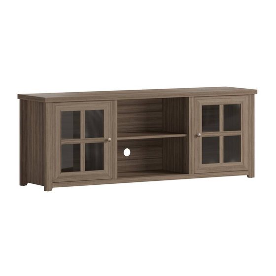
Classic Four Pane Glass Door 65" TV Stand
for up to 80" TVs
Assembly Time
Load Bearing
LBS
LBS
LBS
LBS
| Phone:866-552-2810
Thank you for your purchase!
60 min
200 LBS
LBS
LBS
LBS
30 LBS
LBS
Advertisement

Related Manuals for Belnick GC-MBLK64-GY-GG

Summary of Contents for Belnick GC-MBLK64-GY-GG
- Page 1 To help prevent furniture from tipping over it must be permanently attached to the wall. Anti-Tip Safety Wall Straps suitable for the unit weight and wall materials (if not included) should be purchased and installed. Online Assembly Instructions: http://ftp.flashfurniture.com/AssemblyInstructions/GC-MBLK64-BR-GG.pdf Customer Service Email: CustomerExperience@belnick.com | Phone:866-552-2810 GC-MBLK64-GY-GG/GC-MBLK64-WH-GG/GC-MBLK64-BR-GG...
- Page 2 This warranty will not cover: (1) labor, freight, or damage from misuse, abuse, negligence, alteration, assembly, installation, attachments, accident, vandalism, acts of nature or any other event beyond the control of Belnick; (2) tearing, scratching, scuffing, or blemishing of leather or fabric; (3) cosmetic damage that may result from normal usage; (4) damage attributable to use by persons exceeding specified weight limits or commercial use exceeding forty hours per week;...
- Page 3 PARTS 3.5*14 Left Side Panel Front Fascia Top Plate (1) (11) 36+1 Screws Right Side Panel Front Fascia Bottom Plate (2) (12) Back Panel Screws Left & Right Upper Shelves Door Knob Screws Left Side Panel Back Fascia (3) (13) Note: Ensure slot opening is facing up Middle Shelf...
- Page 4 STEP 1 Insert Long Screw-In Pegs (Part Insert Dowel Pegs B) and turn clockwise with Door Phillips screwdriver to tighten Strike Plates B*20 A*16 Inner Supports Fascia (Part 7) Top Plate (7)*2 (1) Inner Supports (10)*2 (2) Bottom Plate Left Front Fascia (11)...
- Page 5 STEP 3 STEP 3: Ensure Cam Locks (Part D) are inserted in holes with open side facing outwords toward receiver hole for Screw- In pegs (Arrow Side). Insert Long Screw-In Pegs (Part B) at the bottoms of the Left Side Panel (Part 5) and Right Side Panel (Part 6) into the Bottom Plate (Part 2) and Turn Cam Locks clockwise to tighten.
- Page 6 STEP 5 STEP 5: Carefully place frame into an upright position. Place the Lower Rear Panel (Part 9) into the grooves on the Left & Right Side Panels and slide down into the groove on the Bottom Plate. Once seated place the Upper Rear Panel (Part 8) into the grooves on the Left &...
- Page 7 STEP 7 STEP 7: Ensure Cam Locks (Part D) are inserted in holes with open side facing outwards toward receiver hole for Screw-In pegs (Arrow Side). Slide Inner Supports onto Long Screw-In Pegs on the bottom plate ensuring that the Front Fascia are facing Left and Right (See Diagram).
- Page 8 STEP 9 3.5 Screws Door Knob Screw Door Hinges Knob STEP 9B: Attach Door Knobs (Part I) to Front Doors using (2) Door Knob Screws (Part H) (15) STEP 9A: Attach Hinges (Part L) to the inside of the Front Doors (Part 15) using (8) 3.5 Screws (15)...
- Page 9 STEP 11 K*12 Shelf Holders (3) (4) (3) STEP 11: Insert Shelf Holders (Part K) into holes at the desired height then place the Left & Right Shelves (Part 3) and the Middle Shelf (Part 4) onto Shelf Holders STEP 12 Back Panel Screws STEP 12: Attach Upper and Lower Back Panels to the...
Need help?
Do you have a question about the GC-MBLK64-GY-GG and is the answer not in the manual?
Questions and answers