Advertisement
Quick Links
Advertisement

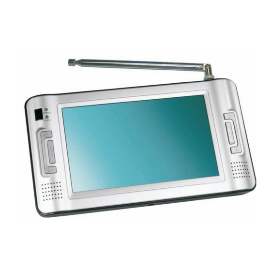
Summary of Contents for Roadstar LCD7080DVBT
-
Page 2: Table Of Contents
CONTENTS 1 Specification .............…........2 Block Diagram .........…............. 3 General Alignment Instruction .............. 4 Troubleshooting ..................5 Printed Circuit Board ................1 6 Explode View ..................7 IC Block Diagram and Lead Identification ......... 8 Schematic Diagram ................1 . -
Page 3: Specification
SPECIFICATION Description Condition Unit Limit Nominal Result Vp-p 0.7 0.1 Video Signal Level Vp-p 0.3 0.1 SYNC Lever 75% collr bar,75ohm Vp-p 1.0 0.2 Video out lever Video out lever Vp-p 1.0 0.2 Audio 1.4 0.2 1.25-1.4 1KHz/0dB out lever Signal-to-noise ratio Infinity Zero/-&dB/l&R... -
Page 4: Block Diagram
BLOCK DIAGRAM ..CCIR0 ..656-D0 656-D0 CCIR7 Vx1827 7 INCH 656-D7 656-D7 PANEL A 8430 TRAN HIGH VOLTAGE M 1206 MAIN PART . 3 . -
Page 5: General Alignment Instruction
GENERAL ALIGNMENT INSTRUCTION The Main PCB of Monitor Modification: 1. Input voltage is 6.8V-16V, input signal is test circuit BY 5418. 2. Adjust VR1 to get good performance. . 4 . -
Page 6: Troubleshooting
TROUBLESHOOTING SYMPTOM CAUSE REMEDY LCD MONITOR PART & Defective IC U2(VX1827) & Replace U2(VX1827) 1) NO Picture & Defective C256 2) NO Picture & Replace C256(10P/3000V) 3) No Picture, Picture no & Replace IC At8430 Cw3406 & Defective IC At8430 Cw3406. Good 4) Luminesce no good &... -
Page 7: Printed Circuit Board
PRINTED CIRCUIT BOARD Monitor HV PCB Top View Bottom View . 6 . - Page 8 PRINTED CIRCUIT BOARD Main PCB Top View . 7 .
- Page 9 PRINTED CIRCUIT BOARD Main PCB Top View . 8 .
-
Page 10: Explode View
EXPLODED VIEW . 9 . - Page 11 IC BLOCK DIAGRAM & DESCRIPTION Vx1827 . 10 .
- Page 12 IC BLOCK DIAGRAM & DESCRIPTION Vx1827 . 11 .
- Page 13 IC BLOCK DIAGRAM & DESCRIPTION A8430EEK . 12 .
- Page 14 8D02D IC BLOCK DIAGRAM & DESCRIPTION S8232 . 13 .
- Page 15 8D02D IC BLOCK DIAGRAM & DESCRIPTION 24C02 . 14 .
- Page 16 8D02D IC BLOCK DIAGRAM & DESCRIPTION CS4334 . 15 .
-
Page 17: Schematic Diagram
SCHEMA TIC DIAGRAMS TFT-POWER . 16 . - Page 18 SCHEMA TIC DIAGRAMS VX1827 . 17 .
- Page 19 SCHEMA TIC DIAGRAMS PANEL . 18 .
- Page 20 SCHEMA TIC DIAGRAMS CHANGE . 19 .
- Page 21 SCHEMA TIC DIAGRAMS POWER . 20 .
- Page 22 SCHEMATIC DIAGRAMS CT212 . 21 .
- Page 23 SCHEMA TIC DIAGRAMS AV-OUT . 22 .


Need help?
Do you have a question about the LCD7080DVBT and is the answer not in the manual?
Questions and answers