Table of Contents
Advertisement
Advertisement
Table of Contents

Related Manuals for Roadstar CTV-1015


Summary of Contents for Roadstar CTV-1015
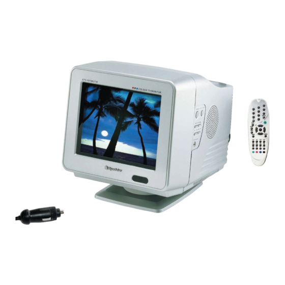
- Page 1 CTV-1015...
-
Page 2: Safety Precaution
SAFETY PRECAUTION X-RAY RADIATION PRECAUTION 1. Excessive high voltage can produce potentially hazardous X-RAY RADIATION. To avoid such hazards, the high voltage must not be above the specified limit. The normal value of the high voltage in this receiver is 18KV. The high voltage must not exceed 25KV. Each time a receiver requires servicing, the high voltage should be checked according to the high voltage check procedure on this manual. -
Page 3: Product Safety Notice
Measure the AC voltage across the combination of 1,500 ohm resistor and 0.15uF capacitor. Reverse the AC plug at the AC outlet and repeat. AC voltage measurements for each exposed metallic part. Voltage measured must not exceed 0.75 volts RMS. This corresponds to 0.5 milliamp AC. Any value exceeding this limit constitutes a potential shock hazard and must be corrected immediately. -
Page 4: Automatic Degaussing
AUTOMATIC DEGAUSSING A degaussing coil is mounted around the picture tube so that external degaussing after moving the TV should be unnecessary. But the receiver must be properly degaussed upon installation. The degaussing coil operates for about 1 second after the power is switched ON. If the set is moved or turned in a different direction, the power should be OFF for at least 15 minutes. - Page 5 FIG. B-1 CONVERGENCE MAGNET ASSEMBLY Vertical Green Belt ADJUST FIG. B-2 CENTER CONVERGENCE ADJUSTMENT BLUE BLUE BLUE BLUE/RED GREEN 4-POLE MAGINETS MOVEMENT 6-POLE MAGINETS MOVEMENT FIG. B-3 CENTER CONVERGENCE ADJUSTMENT...
-
Page 6: Specifications
SPECIFICATIONS PAL SECAM BG/DK I L & NTSC Playback RECEPTION SYSTEM AC 90-250V~ 50/60Hz, 45W POWER SOURCE DC 12-24V , 40W 1.0W SOUND OUTPUT POWER 75 OHM UNBALANCED TYPE ANTENNA IMPEDANCE OPERATING FREQUENCIES VIDEO IF 38.9MHz SOUND IF 33.4MHz RECEIVING CHANNELS CH : 2 TO 4 CH : 5 TO 12 UHF CH : 21 TO 69... -
Page 7: Location Of Controls
LOCATION OF CONTROLS FRONT BACK 1. STAND-BY LAMP 8. Earphone Jack 2. Remote Control Sensor 9. Antenna Holder 3. Power Switch 10. Antenna Jack(75 ohm) 4. TV/ VIDEO Key 11. Scart Jacks 5. Speaker 12. AC Input Jack(Mains Power Socket) 6. -
Page 8: Remote Control Use
REMOTE CONTROL USE BATTERY INSTALLATION Replace two batteries in the battery compartment at the same time. lnsert "AAA" batteries, observing the polarity ( ) marked on the unit. Batteries should last about a year under normal use. lf the operation is unstable(either channel or volume does not change), replace the batteries. -
Page 9: Basic Remote Control Operation
BASIC REMOTE CONTROL OPERATION 1. Power button At Stand-by mode, the LED stand-by indicator is in RED color. By pressing the power button, the TV will be turned ON, and the LED stand-by indicator will be turned OFF. 2. TV/Video button Select either TV or VIDEO mode. - Page 10 BASIC REMOTE CONTROL OPERATION 10. Menu button It displays all the functions that user can control. 11. Sleep button The television is automatically turned off after an elapse of the set sleep time. 1) The set time ranges from 10 to 180 minutes, which is repeated in sequence each time you press. SLEEP OFF 2) If you'd like to check the remaining SLEEP TIME after OSD disappears, press DISPLAY button.
- Page 11 GENERAL FEATURES AND ADJUSTMENTS 1. NOTE Because this is not a hot chassis, it is not necessary to use an isolation transfromer. However, the use of isolation transformer will help protect test instrunents. Adjustment must be done in the correct order. Supply AC 90-250V~ 50/60Hz, 45W, DC 12-24V , 40W in general.
- Page 12 FACTORY/SERVICE ADJUSTMENTS 1. Procedure for the factory adjustment mode In the ON mode, the factory(Service) mode is activated by pressing the DISPLAY + 1 + 1 + TV/Video button in sequence on the remote controller. The menu of the factory mode will be displayed. The factory mode consists of 9 componets: 1.
- Page 13 FACTORY/SERVICE ADJUSTMENTS PART RANGE INITIAL DATA COMMENT SERVICE 2 CONTRAST 0~63 0 35 55 Min Cnt Max BRIGHT 0~63 0 30 50 COLOR 0~63 0 28 63 SHARPNESS 0~63 0 24 48 TINT 0~63 0 32 63 0~63 VOLUME TEST MIN / MAX Device Check Connected...
-
Page 14: Focus Adjustment
FACTORY/SERVICE ADJUSTMENTS 3. Deflection Adjustments HRS(50) adjustment : Tune the TV set to a LION HEAD pattern signal with 50Hz of vertical frequency. HRS(60) adjustment : Tune the TV set to a LION HEAD pattern Signal with 60Hz of vertical ferquency. HEIGHT adjustment : Tune the TV set to a LION HEAD pattern Signal and adjust the vertical amplitude to... -
Page 15: Stereo Amplifier
6+6W STEREO AMPLIFIER TDA 2007A DESCRIPTION The TDA2007A is a class AB dual Audio power amplifier assembled in single in line 9 pins package, specially designed for stereo application in music centers TV receivers and portable radios. Features HIGH OUTPUT POWER HIGH CURRENT CAPABILITY AC SHORT CIRCUIT PROTECTION THERMAL OVERLOAD PROTECTION... - Page 16 6+6W STEREO AMPLIFIER TDA2007A ABSOLUTE MAXIMUM RATINGS Symbol Parameter Value Unit Supply Voltage Output Peak Current (repetitive f ≥ 20Hz) Output Peak Current (non repetitive t = 100µs) Power Dissipation at T = 70°C case °C Storage and Junction Temperature - 40 to 150 ELECTRICAL CHARACTERISTICS (refer to the stereo application circuit, T = 25°C, V...
- Page 17 Power Switching Regulator STR-G5653 DESCRIPTION STR-G 5653 is a hybrid IC with a built-in MOS FET and control IC, designed for a primary side regulation. MANY PROTECTION FUNCTIONS OVP(over voltage protection circuit) OCP(over current protection circuit) TSD(Thermal shutdown circuit) BLOCK DIAGRAM PIN CONFIGURATION SYMBOL Description...
-
Page 18: Quick Reference Data
Full bridge vertical deflection output circuit in LVDMOS TDA8357J FEATURES GENERAL DESCRIPTION The TDA8357J is a power circuit for use in 90° and 110° Few external components required High efficiency fully DC coupled vertical bridge output colour deflection systems for 25 to 200 Hz field circuit frequencies, and for 4 : 3 and 16 : 9 picture tubes. -
Page 19: Block Diagram
Full bridge vertical deflection output circuit in LVDMOS TDA8357J BLOCK DIAGRAM... - Page 20 TUNER TECC2949PG35E 1. APPLICATIONS Reciving System : CCIR Standard system Channel : VHF Low band : NZ1 (45.25MHz) ~ S6 (140.25MHz) VHF High band : S7 (147.25MHz) ~ S36 (423.25MHz) UHF band : S37 (431.25MHz) ~ E69 (855.25MHz) Intermediate Frequency PIF : ( 38.90 )MHz CIF : ( 34.47 )MHz SIF : ( 33.40 )MHz Input Impedance : UHF/VHF Terminal (75) , Unbalanced...
-
Page 21: Electrical Characteristics
TUNER TERMINAL FOR EXTERNAL CONNECTION ELECTRICAL CHARACTERISTICS... - Page 22 TUNER RECEIVING CHANNEL FREQUENCY TABLE...
- Page 23 TUNER RECEIVING CHANNEL FREQUENCY TABLE...
- Page 24 TUNER RECEIVING CHANNEL FREQUENCY TABLE...
- Page 25 TV Signal processor- Teletext decoder with embedded -controller TDA935X/6X/8X PS/N2 Series General description & features General description & features TDA 9361/9381 PS/N2 combine the functions of a TV signal TDA 9361/9381 PS/N2 combine the functions of a TV signal processor together with a -controller and US Closed Caption processor together with a -controller and US Closed Caption Decoder.
- Page 26 TV Signal processor- Teletext decoder with embedded -controller TDA935X/6X/8X PS/N2 Series BLOCK DIAGRAM...
- Page 27 TV Signal processor- Teletext decoder with embedded -controller TDA935X/6X/8X PS/N2 Series PINNING SYMBOL DESCRIPTION P1.3/T1 Power(ACTINE LOW) ON:LOW, STAND-BT:HIGH P1.6/SCL Serial CLOCK P1.7/SDA Serial DATA P2.0/TPWN SVHS MODE DETECTION INPUT(ACTIVE LOW) P3.0/ADC0 NTSC SYSTEM CONVERSION OUTPUT(ACTIVE LOW) P3.1/ADC1 AUDIO/VIDEO MODE SWITCH 1 P3.2/ADC2 CONTROL BUTTON KEY INPUT 1 P3.3/ADC3...
- Page 28 TV sound AM-demodulator and audio source switch TDA9830...
- Page 29 TV sound AM-demodulator and audio source switch TDA9830...
- Page 30 TV sound AM-demodulator and audio source switch TDA9830...
-
Page 31: General Description
Triple Video Output Amplifier TDA6107Q GENERAL DESCRIPTION The TDA6107Q includes three video output amplifiers in one plastic DIL-bent-SIL9-pin medium power(DBS9MPF) package (SOT111-1), using high-voltage DMOS technology, and is intended to drive the three cathodes of a colour CRT directly. To obtain maximum performance, the amplifier should be used with black-current control. - Page 32 Triple Video Output Amplifier TDA6107Q SYMBOL DESCRIPTION incerting input 1 i(1) incerting input 2 i(2) incerting input 3 i(3) ground (fin) black-current measurement output supply voltage cathode output3 Voc(3) cathode output2 Voc(2) cathode output1 Voc(1)
-
Page 33: Troubleshooting
TROUBLE SHOOTING 1. NO POWER (The secondary of the SMPS transformer) START Check the output voltage of MAIN PCB STAND-BY IC52, IC83. IC52 3.3V 3.3V Check the cathode voltage of IC83 4.97V 4.97V D803. D803 16.2V 16.2V Check all the electric leakage in each voltage with multi-meter. - Page 34 TROUBLE SHOOTING 2. NO RASTER (The power is normal but the heater voltage is “LOW”) START Check the output voltage of Check the voltage between pin 1 of IC51 IC52, IC83, and IC53. and GROUND. Is it Low ? Check the waveform of X001(12MHZ).
- Page 35 TROUBLE SHOOTING 3. NO PICTURE (SOUND is OK) START Check pin 7,8,9 of IC91 in CPT PCB. Check the pin 1,2,3 of IC91. Check pin 51,52,53 waveforms of IC51. Check pin 38 waveforms of IC51. Check the pin 40 waveforms of IC51.
- Page 36 TROUBLE SHOOTING 4. NO SOUND (PICTURE is “OK”) START See that the sound state is MUTE Check the waveform between of IC61 and GROUND. Check the waveform between 1 of IC61 and GROUND See that the mode state Replace IC61 with new one. (pin 3 of IC62 is HIGH ) (MUTE:LOW, normal:HIGH) FM MONO...
- Page 37 TROUBLE SHOOTING 5. Vertical Line START Check the Supply voltage at pin 3 of IC31 Check D382. V2=DC13.7V Check the waveform at pin 4 & 7 of IC31. Check the waveform of the posive sawtooth(pin1) and negative Check IC31 and Peripheral sawtooth(pin2) of IC31.
- Page 38 BLOCK DIAGRAM...
-
Page 39: Electrical Parts List
ELECTRICAL PARTS LIST P / No. ITEM No. ITEM NAME P / No. ITEM No. ITEM NAME A001 150032377 “MAIN, PAL PTQM03 I10JQ6RST” EL03 11061303 “EYELET, HTR 2.80*2.9 SNI” A001A 150032378 “MAIN, PAL PTQM03-1 I10JQ6RST” EL04 11061303 “EYELET, HTR 2.80*2.9 SNI” AA01U 150130995 “MAIN, AUTO PTQM03-1 I10JQ6RST”... - Page 40 ELECTRICAL PARTS LIST P / No. ITEM No. ITEM NAME P / No. ITEM No. ITEM NAME J017 11183004 “PLATING WIRE, 0.6MM” J105 11183004 “PLATING WIRE, 0.6MM” J018 11183004 “PLATING WIRE, 0.6MM” J106 11183004 “PLATING WIRE, 0.6MM” J019 11183004 “PLATING WIRE, 0.6MM” J111 11183004 “PLATING WIRE, 0.6MM”...
- Page 41 ELECTRICAL PARTS LIST P / No. ITEM No. ITEM NAME P / No. ITEM No. ITEM NAME R205 12368331T “CARBON RESISTOR, SB 1/6W 330 OHM J” R890 12005475T “SURGE RES(VDE),1/2W 4.7M OHM” R221 12368153T “CARBON RESISTOR, SB 1/6W 15K OHM J” R891 12005475T “SURGE RES(VDE),1/2W 4.7M OHM”...
- Page 42 ELECTRICAL PARTS LIST P / No. ITEM No. ITEM NAME P / No. ITEM No. ITEM NAME C609 12794471T “CHEMICON, 16V 470MF 85C 10*13” D823 11115748 “DIODE, UFR FML22S” C611 12797229T “CHEMICON, 50V 2.2MF 85C 5*11” D823A 11865602 “HEAT SINK, 20LX (45MM)” C612 12794221T “CHEMICON, 16V 220MF 85C 8*12”...
- Page 43 ELECTRICAL PARTS LIST P / No. ITEM No. ITEM NAME P / No. ITEM No. ITEM NAME T882 11213401A “TRANS, SMPS KPW-1180 10GN” C993 12794102T “CHEMICON, 16V 1000MF 85C 10*20” TU01 11121229A “TUNER, TECC2949PG35F IIC DIN” D991 11114647 THYRISTOR TF361M TU01 11121238 “TUNER, TAEM-G104D”...
- Page 44 11115729T “DIODE, RK-36 V1 SANKEN” K101G P1827337A S/W PANEL 10AJ (S-006) EL81 11061303 “EYELET, HTR 2.80*2.9 SNI” K101H 11819093 “PLATE, B/M (DIA) ROADSTAR 10”(L)” EL82 11061303 “EYELET, HTR 2.80*2.9 SNI” K104 11035310 “SCREW, BTB 3*10 SZN” EL83 11061303 “EYELET, HTR 2.80*2.9 SNI”...
- Page 45 C1124053 “ROD-ANT, 4SEC 800MM (2POLE) F660MM” Y202 11176137 “CORD DC CAR, 4.0A 125/250V UL/CSA” Y203 11176229 “CORD AC, KKP-419J/KKS-15A (GP)” Y222 390110709 “R/CON, RN3200H(S) ROADSTAR 10JQ6RST” Y301 11843106A “TILT ASS’Y, 10AJ (S-006)” Y301A 11933486 EPS PAD Y301B 11843088A “LEAD PLATE, BM10CG”...
Need help?
Do you have a question about the CTV-1015 and is the answer not in the manual?
Questions and answers