Table of Contents
Advertisement
Copyright 1994-96
ONLINE OWNERS MANUAL
INSTALLERS!!! THIS DOCUMENT IS IMPORTANT FOR
OPERATION, PLEASE LEAVE IT WITH THE OWNER!!!
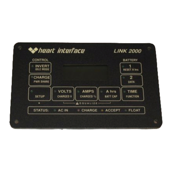
The LINK 2000 is an integrated battery monitor and inverter/
charger control. It displays the critical information necessary for 12V
or 24V DC system battery management and allows precise control of
critical inverter and charger features.
The LINK 2000 may be used as a stand-alone battery monitor or
with the following inverter/chargers from HEART INTERFACE:
FREEDOM 10 INVERTER/CHARGERS
FREEDOM 15 INVERTER/CHARGERS
FREEDOM 20 INVERTER/CHARGERS
FREEDOM 25 INVERTER/CHARGERS
FAST START: For installation details skip to the Required
Reading section on page 34. Please read manual prior to using.
All warranty issues must be resolved through Heart Interface or Cruising
Equipment Co. Please do not return to the retailer, or route warranty issues
through the retailer.
Mfg. by
Manual Part # 890024
LINK 2000
th
21440 68
(206) 872-7225 Toll Free 1-800-446-6180
6315 Seaview Ave. NW Seattle, WA 98107
C:\work\link\link2000new\newinstall.pm6
Ave. So. Kent, WA 98032
(206) 782-8100
5/31/96
1
Advertisement
Table of Contents

Related Manuals for Heart Interface LINK 2000

Summary of Contents for Heart Interface LINK 2000
- Page 1 It displays the critical information necessary for 12V or 24V DC system battery management and allows precise control of critical inverter and charger features. The LINK 2000 may be used as a stand-alone battery monitor or with the following inverter/chargers from HEART INTERFACE: FREEDOM 10 INVERTER/CHARGERS...
-
Page 2: Specifications
Monitor Set Up Page 9 Functions Set Up Page 10-14 Data Page 15 How to Use Link 2000 Meters Page 16-17 Ideal Charge Curve Page 18 Synchronizing to a Full Battery (Resetting A hrs to Zero) Page 19-20 Selecting The Charged Parameters... - Page 3 3) When used in a mixed voltage (12V & 24V) system, Battery #1 is the battery that the LINK uses for voltage regulation. Make sure it is the battery that is used by the Inverter/Charger, or with the LINK 2000-R option it must be the battery being charged by the alternator. See Functions Mode F11.
-
Page 4: Monitor Functions
5/31/96 MONITOR FUNCTIONS Please also refer to the one page summary of features in center of this manual. The small blue legends indicate Set Up functions described later. BATTERY SELECT The battery to be monitored is LO BAT selected by pressing the #1 or #2 switch. - Page 5 5/31/96 For the TIME function to operate correctly you must enter your battery capacity through the SET UP routine (see Page 9). You must also set up the correct Peukert's exponent (see Page 13). Caution: The TIME display is an estimate of how long your battery can sustain a load.
-
Page 6: Status Line
AC power is interrupted. NOTE: To terminate Equalize early on Freedoms manufactured prior to serial #100,000 you must turn off BOTH the Charger and Inverter on the LINK 2000. Equalizing causes the battery to gas. You should check your battery electrolyte before and after equalization. - Page 7 5/31/96 SET UP The LINK 2000 has been set up with default values chosen to work with a typical system. Normally the only values that must be changed are: 1) Battery capacity (Page 9) 3) Battery type (liquid or gel) (F02 Page 10).
- Page 8 5/31/96 INVERTER SET UP IDLE MODE: The default value is 4 Watts. This means it takes a 4 Watt AC load to turn the inverter ON from its low power idle mode. Setting a value of 0 Watts means the inverter is always ON. The low idle current is about 0.12 Amps. When idle mode is set to 0W the current consumption goes up to about 0.3 Amps.
-
Page 9: Monitor Setup
The default Charged Voltage is 13.2 Volts for 12 Volt systems and 26.4 Volts for 24 Volt systems. The LINK 2000 automatically selects the correct value based on the volt- age it senses. (If the Alternative Energy function F05 is ON, the default value is 13.5 Volts or 27.0 Volts. -
Page 10: Functions Set Up
LED by the FUNC button stops flashing. You may now choose any blue key to continue setting up the Link 2000. If you press the FUNC button again the process will begin at the next function after the one you last set up. Whatever functions you have set up will become active when the display reverts to its normal mode. - Page 11 5/31/96 F02 - BATTERY TYPE This function allows the choice of liquid or gelled electrolyte batteries. 1 = WET (LIQUID) ELECTROLYTE (DEFAULT) 2 = GELLED ELECTROLYTE The default value is Type #1 which is equal to a liquid electrolyte lead acid battery. To select Type #2, which is for gelled electrolyte lead acid batteries, simply go through the normal set up procedure.
- Page 12 DEFAULT OFF = NORMAL TWO BATTERY MONITORING MODE ON = BATTERY/SOURCE MONITORING MODE Turn this mode on with LINK 2000 Meters used in Alternative Energy Systems. This function selects between the normal two battery monitoring mode and the battery/source monitoring mode. When this mode is OFF, the meter works as a two battery monitor as described previously.
- Page 13 This function is used to defeat Battery #2 as a part of the charger control function of the Link 2000. This is necessary for systems that have both 12V and 24V batteries. Battery #1 must be the battery that is used by the Freedom inverter (or charged by the alternator when controlled by the Link 2000R).
- Page 14 5/31/96 F12 - BACKLIGHTING INTENSITY CONTROL DEFAULT = 130 RANGE = 0 - 240 STEP = 10 This function may be used to increase or decrease the intensity of the backlighting for the display. F13 - F14 NOT USED F15 - Special Function for use by Cruising Equipment. DEFAULT ON = INVERTER CONTROL OFF = ASCII OUTPUT CAUTION!! LEAVE THIS FUNCTION ON.
- Page 15 5/31/96 DATA DATA: The DATA mode is used to recall key historical information about the battery (battery banks). To access the DATA mode: 1) Select Battery #1 or #2 to review its data. 2) Press and hold the SET UP button until the green LED begins to flash then release the button.
- Page 16 LINK 2000 Meter to 100% charged batteries. . You would use battery #1 until the LINK 2000 Meter showed that you had used 50% (the display would show -100A hrs). You would then use battery #2 until you had used 50% of it (-100A hrs). At this point charge both batteries up to about the 85% level (-30 A hrs on each).
- Page 17 Assume a 12V battery rated at 100 A hr. Apply a 5 amp load. Suppose it only took 10 hours for the voltage to reach 10.50 volts. LINK 2000 would display -50 A hr. This is the 10 hour capacity. Dividing 50 by 89% (10 hour rate) from the table above, you determine that the actual 20 hour capacity is 56 Amp-hours.
- Page 18 5/31/96 IDEAL CHARGE CURVE The LINK 2000 transmits critical battery state of charge information to the Freedom inverter/charger (and controls the alternator with the Link 200-R option). This enables the charger to conform to our proven Ideal Charge Curve with four basic cycles;...
-
Page 19: Charged Parameters
A hrs removed. The following charged parameters indicate when a charging system has put as much energy into a battery as it normally can. Your LINK 2000 Meter must be synchronized to the battery according to these parameters. - Page 20 LINK 2000 automaticaly resets to zero, starts counting down, and is in sync. If the LINK 2000 Meter should ever get out of sync with the battery state of charge it must be resynchronized. The best way is to be sure the battery is discharged at least 10% of the declared battery capacity and then recharge until the charged parameters are met.
- Page 21 13.2 Volts and the current falls below 4 Amps, for five minutes, the LINK 2000 considers the battery full. The LINK 2000 learns the Charge Efficiency Factor (CEF) of the battery based on the Charged Parameters. A CEF of greater than 100% is not allowed. To trigger a recalculation of the CEF, the battery must be discharged at least 10% of declared capacity.
- Page 22 If the charged parameters are not correctly selected, the LINK 2000 will never recalculate the CEF. For example: (1) If your charging system only reaches 13.8Volts, a Charged Voltage of 14.0 Volts will not work.
-
Page 23: Advanced Functions
5/31/96 ADVANCED FUNCTIONS The drawing below shows the Advanced Functions layout. To access these press the SET UP BUTTON for ten seconds. The time is long to avoid unintentionally entering this mode. When the green LED begins to flash quickly (about 3 times per second) select the Advanced Function you wish by consulting this drawing. - Page 24 Making two discharge tests, one at a high discharge rate and one at a low rate, that bracket your normal range of operation, allows you to calculate an "n" that will describe this varying effect. The LINK 2000 uses a default value of "n" equal to 1.25 which is typical for many batteries.
- Page 25 5/31/96 HIGH DISCHARGE RATES & PEUKERT'S EQUATION The table below may be used to understand the effect of high rates of discharge on available battery capacity. It may also be used to estimate the exponent "n" for a battery after a single discharge test. The table is based on a 100 Ahr battery but may be used for any capacity battery by using an appropriately scaled current.
-
Page 26: Typical Peukert's Exponents
5/31/96 TYPICAL PEUKERT'S EXPONENTS The following table contains values for the exponent "n" for various batteries and manufacturers. They are calculated from the 20 hour rating and the Reserve Minutes @ 25A as supplied by the manufacturer. Page 27 shows how the calculation is performed. You may choose a battery of similiar size and construction as a guide in selecting "n"... - Page 27 5/31/96 TYPICAL PEUKERT'S EXPONENTS Surrette and Rolls Batteries Model Volts Res. Min. 20 Hr. Rating "n" EHG-208 1.42 EIG-225 1.54* EIG-262 1.72* 24/90 1.16 27/12M 1.23 30H/108 1.08 HT/4D 1.15 HT/8D 1.20 *Use Max allowed "n" of 1.50 CALCULATING PEUKERT'S EXPONENT Example of using Reserve Minutes @ 25 Amps and the 20 hour rate to calculate "n".
-
Page 28: Error Codes And Troubleshooting
5/31/96 ERROR CODES AND TROUBLE SHOOTING The following error codes are displayed when the LINK 2000 detects a problem. The display alternates between the selected monitoring function and the Error Code. The Error Code continues to flash until the error is corrected. (Error codes same for all models.) - Page 29 LINK 2000 DEPOWERED: Displayed on power up and when power has been interrupted or dipped below the operating voltage of the Link 2000. May be caused by voltage dips during engine starting if the meter is powered by starting battery.
- Page 30 5/31/96 MICROPROCESSOR RESET PROCEDURE The LINK 2000 uses a microprocessor to perform all of its calculations and functions. We have worked very hard to insure a stable trouble-free product, however like all computer products the unit is sometimes susceptible to power supply dips or surges that can cause erratic behavior or memory errors.
- Page 31 Follow the procedure outlined on the previous page to first reset the microprocessor. Select Battery bank #1 on the LINK 2000 to reset to factory values for Battery #1. To also reset Inverter and Charger functions to factory defaults be sure that the INVERT and CHARGE LEDs are lit.
- Page 32 5/31/96 SET UP & HISTORICAL DATA SUMMARY The following table is a summary of the values that may be changed through set up or by accumulating historical data. The column on the right is provided to write down your set up values or historical data. Be sure and know these values before calling for customer service.
- Page 33 Cruising Equipment Co. (CECO) warrants to the original purchaser only for 30 months from the date of purchase that LINK 2000, and LINK 2000R Meters (hereafter Meter) will be in good working order when properly installed and operated as described in this Manual.
-
Page 34: Required Reading
All wiring should be done before installing the fuse. GENERAL NOTES 1) Wiring to the LINK 2000 Meter should be #16 or #18 AWG. (Larger is OK, but not necessary.) Wiring should be per NEC or applicable standards. 2) The Shunt Sense Leads should be a twisted pair. Leads up to 1,000 feet long may be used if they are not run along with other noise producing conductors. - Page 35 5/31/96 output alternators are available and we strongly recommend them. With isolated negative output alternators, remember that instrumentation and other loads grounded directly to the engine block will not be measured unless their negatives are relocated to the load side of the Battery Shunt. Special high current shunts are also a solution and may be ordered from us.
- Page 36 There are three phone plugs on the back (bottom) of the inverter. Use the one labeled REMOTE. It is best to plug the phone cord into the LINK 2000 after it is powered up. It is supplied with a 25' cord. You may purchase longer cords from any telephone supply company.
Need help?
Do you have a question about the LINK 2000 and is the answer not in the manual?
Questions and answers