Table of Contents
Advertisement
Quick Links
WiiChuck Kit Instructions
Page 1 of 6
Important Information
Congratulations and thank you for your purchase of the
Delptronics WiiChuck module kit!
Once you have built the kit, download the
User Manual
to learn how to use all of the features.
Before you start, please read the
Electronic Kit
Soldering
Tutorial. It contains important and useful
information even for experienced kit builders. This is a
good first electronic kit. It is relatively straightforward to
assemble, and there are not that many different parts.
Take your time and be careful to put the right part in the
right place, and, where applicable, in the right
orientation. It is difficult to de-solder parts if you make a
mistake.
The parts for the kit are in multiple bags. One or more
bags contain discreet components like resistors and
capacitors, and the other bag contains
electromechanical parts like jacks, and buttons. The
discreet components are soldered first. Before you start,
separate the parts by type. When you are ready to
solder parts of a particular type, separate them by
value. In general, the order that the parts are soldered
onto the PCB is shortest to tallest.
The complete bill of materials (parts list) is on the last
page of this document.
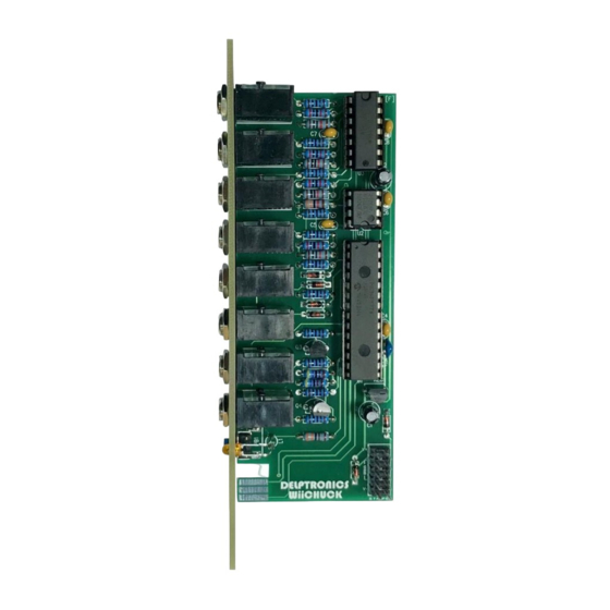
The PCB is marked with the part refdes (reference
designator), For example, R1 refers to resistor number
one and C1 refers to capacitor number one. In the case
of the resistors, the value is also printed on the PCB.
Refer to the picture of an assembled kit to the right for
guidance on part placement and orientation.
Advertisement
Table of Contents

Related Manuals for Delptronics WiiChuck


Summary of Contents for Delptronics WiiChuck
- Page 1 WiiChuck Kit Instructions Page 1 of 6 Important Information Congratulations and thank you for your purchase of the Delptronics WiiChuck module kit! Once you have built the kit, download the User Manual to learn how to use all of the features.
- Page 2 WiiChuck Kit Instructions Page 2 of 6 Resistors The value of a resistor is indicated by colored stripes on its body. In all cases the fifth stripe is brown (indicating 1% tolerance), so that stripe has been omitted from the chart below. In addition to the refdes, the resistor value is printed right on PCB.
- Page 3 WiiChuck Kit Instructions Page 3 of 6 Diodes There are 6 diodes. They are the same type (BAT85). The diodes are red and black glass tubes. When inserted into the PCB, the black side of the diode must line up with the stripe on the part outline on the PCB. The diode leads need to be bent close to the body of the diode.
- Page 4 WiiChuck Kit Instructions Page 4 of 6 Voltage Regulator There is one voltage regulator (refdes REG1). It is marked KY5033. They have the same shape as a transistor, so make sure that you look at the part marking to verify which one is the regulator, Make sure that the flat side of the part lines up with the flat side of the outline on the PCB.
- Page 5 WiiChuck Kit Instructions Page 5 of 6 Power Header The power header does not snap in and will not stay in place by itself. Insert the shorter pins into the PCB, and flip the PCB over onto your work surface. Solder only one pin. Then, turn the PCB over and check to make sure that the header is flush against the PCB.
- Page 6 WiiChuck Kit Instructions Page 6 of 6 Complete! Congratulations! Your WiiChuck module is now assembled and useable. Bill of Materials Name Value Quantity RefDes Schottky Diode BAT85 D1, D2, D3, D4, D5, D6 Resistor R2, R3, R4, R5, R6, R7, R10, R11, R12, R13, R14...
Need help?
Do you have a question about the WiiChuck and is the answer not in the manual?
Questions and answers