Advertisement
Quick Links
ThunderBell Module Kit Instructions
Page 1 of 8
Important Information
Thank you for your purchase of the Delptronics ThunderBell Eurorack Module Kit!
The most recent version of this document, and the instructions for the ThunderBell Mini Kit can be downloaded from:
http://delptronics.com/thunderbell.php
Before you start, please read the Electronic Kit Soldering Tutorial. It contains important and useful information even
for experienced kit builders. If this is your first electronic kit, the best piece of advice we can give is to take your time
and be careful to put the right part in the right place. The tutorial can be downloaded from:
http://delptronics.com/documents/SolderingTutorial.pdf
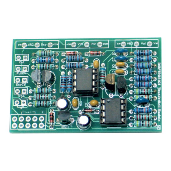
In the instructions that follow, each part type is followed by the PCB outline for that part. Refer to the enclosed
photograph of the completed kit for assistance with part identification and placement.
The PCB is marked with the refdes (reference designator) of each part, not its value. For example R1 refers to
resistor number one and C1 refers to capacitor number one. Once the part value is identified, it is easy to find the
refdes on the PCB.
Some parts must be oriented in a particular way, that is, the correct lead goes in the appropriate hole in the PCB. For
example, electrolytic capacitors are polarized (they have a positive lead and a negative lead). Ceramic capacitors are
not polarized, so it does not matter which of the two leads goes in which of the two holes. In these instructions, the
symbol (±) highlights parts that must be inserted with a particular orientation.
When you are ready to begin, separate the parts by type. Then, when you are ready to solder parts of a particular
type, separate them by value. Compare your parts to the bill of materials, which can be found on the last page of this
document. Make sure no parts are missing. These instructions list the parts in the recommended order of assembly.
In general, the order is shortest to tallest.
This manual is separated into two sections: board-mounted parts, which are soldered directly to the PCB, and off-
board parts which are connected to the PCB via wires.
Using the ThunderBell Module
Trigger Button: Press the button to make the bell sound.
Pitch Knob: controls the pitch of the bell.
Decay Knob: controls how long it takes for the bell's volume to decay from its maximum level down to silence. The
bell can be re-triggered even while the last bell sound is still decaying.
Pitch CV Jack: allows you to control the pitch of the bell with an external control voltage. It accepts 0V to 5V, but has
over-voltage protection. The pitch is determined by the sum of the voltage in the jack and the pitch knob, so the knob
still works when a plug is inserted into the jack.
Decay CV Jack: allows you to control the decay of the bell with an external control voltage. It accepts 0V to 5V, but
has over-voltage protection. The decay is determined by the sum of the voltage in the jack and the pitch knob, so the
knob still works when a plug is inserted into the jack.
Trigger Jack: allows you to trigger the bell sound using an analog trigger or gate signal. It accepts a 2.5 to 15 volt
signal. The trigger button can still be used even when a plug is inserted into the Trigger Jack.
Output Jack: is where the sound comes out. The output signal is about 9V peak-to-peak.
Advertisement

Related Manuals for Delptronics ThunderBell


Summary of Contents for Delptronics ThunderBell
- Page 1 Important Information Thank you for your purchase of the Delptronics ThunderBell Eurorack Module Kit! The most recent version of this document, and the instructions for the ThunderBell Mini Kit can be downloaded from: http://delptronics.com/thunderbell.php Before you start, please read the Electronic Kit Soldering Tutorial. It contains important and useful information even for experienced kit builders.
- Page 2 ThunderBell Module Kit Instructions Page 2 of 8 Board-mounted Parts All of the board-mounted parts are supplied in two little plastics bag to keep them together. You can refer to the picture below while assembling the printed circuit board. The following pages list each part type and describe how to assemble it.
- Page 3 ThunderBell Module Kit Instructions Page 3 of 8 1N4148 Diode (±) Diodes are red and black glass cylinders. There are four diodes, and they all look similar, but D2 is different. D2 is a switching diode and has “1N4148” printed on it in very small type. An easier way to tell D2 apart is that D2 is loose, while the other three diodes are connected together on a piece of tape.
- Page 4 ThunderBell Module Kit Instructions Page 4 of 8 Chip Sockets (±) There are two 8-pin sockets. Sockets are marked with a small notch on one end that must line up with the notch in the PCB outline. Once the socket is soldered in place, the PCB outline will not be visible, so it is important that the socket is oriented correctly in order to ensure that the chip is oriented correctly when it is inserted into the socket.
- Page 5 ThunderBell Module Kit Instructions Page 5 of 8 Power Connector The power connector is a black plastic block with ten pins sticking out of it. The shorter pins get inserted into the PCB and soldered. Make sure that the plastic body of the connector is flush against the PCB. A good technique is to solder only one pin.
- Page 6 ThunderBell Module Kit Instructions Page 6 of 8 Connecting Off-Board Parts via Wires The placement of pots, jacks, and switches in the panel or enclosure determines how and when they are connected to the PCB as well as the length of wire needed. Cut a piece of wire to the appropriate length. Measure carefully, and give yourself a little extra wire to work with.
- Page 7 Then do the same with the jacks and button. When all the parts are in place, tighten the nuts. Take care not to scratch the front of your panel. The last thing to do is to put knobs on the pots. Finished Congratulations, your ThunderBell module is ready to make sweet music!
-
Page 8: Bill Of Materials
ThunderBell Module Kit Instructions Page 8 of 8 Bill of Materials Board-mounted Parts: Quantity Description Marking on part Refdes BAT85 Schottky Diode BAT85 D1, D3, D4 1N4148 Diode 1N4148 1K Resistor brown black black brown R10, R11, R14, R15, R16 4.7K Resistor...
Need help?
Do you have a question about the ThunderBell and is the answer not in the manual?
Questions and answers