Table of Contents
Advertisement
Quick Links
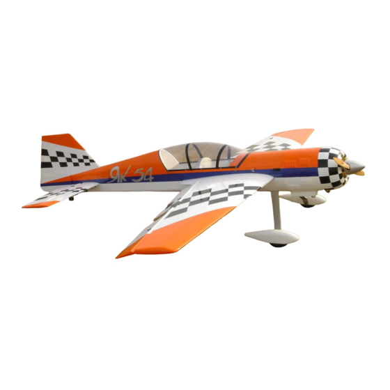
33% YAK 54 Assembly Manual
For assistance contact :
Aviation Models
25022 104th Ave SE, Suite E
Kent, WA 98030
Product Information:
Ordering Hotline:
Copyright © 2005 by Aviation Models, Inc. All rights reserved.
please report errors to
Aviation Models
Second edition rev. 6.02.18
1-253-332-0786
1-866-877-8621
sales@toc1.com
1
Advertisement
Table of Contents

Related Manuals for Aviation Models YAK 54


Summary of Contents for Aviation Models YAK 54
- Page 1 For assistance contact : Aviation Models 25022 104th Ave SE, Suite E Kent, WA 98030 Product Information: 1-253-332-0786 Ordering Hotline: 1-866-877-8621 Copyright © 2005 by Aviation Models, Inc. All rights reserved. Second edition rev. 6.02.18 please report errors to sales@toc1.com...
- Page 2 Warranty Information: Aviation Models, Inc. guarantees this kit to be free of defects in both material and workmanship at the time of purchase. This warranty does not cover any components damaged by use or modification. In no case shall Aviation Models, Inc.
- Page 3 Warning. This is not a toy. If not properly controlled it can cause injury or death and property damage. Operation of this model should at all times be in compliance with Academy of Model Aeronautics safety rules. CANISTER READY, COWL RING MOUNT, PRE-HINGE-SLOTTED S U RFACES, PUSH-RODS AND CONTROL LINKAGES, 5”...
-
Page 4: Table Of Contents
Table of Contents Page Subject Open and inspect everything Using This Manual Hinging Mount Aileron Servos Aileron Linkage Install the Landing Gear Engine Mounting Engine Pictures Hinging the Rudder Rudder Servo/Pull-Pull System Elevator Servos and Linkage Wheel Pants Fuel Tank /Throttle/Choke Prepare and Mount Cowl Canopy Mount the wings... -
Page 5: Open And Inspect Everything
Step 1. Open and inspect everything This section should be fairly self explanatory. In the large box you should have a fuselage with hatch., wing tube and dual stab tubes, the elevator/stab assemblies, the rudder, cowl, wheel pants, canopy, and a package with the landing gear, tail wheel bracket and miscellaneous nuts and bolts. -
Page 6: Using This Manual
Using This Manual When you start a construction section, it is a good idea to first read that entire section before cutting or drilling or gluing. For example, if you are about to begin the section called “Mount the Hatch and Canopy”, then read that entire section before doing anything else. -
Page 7: Hinging
Hinging Hinging is a very simple matter. We recommend that you hinge all the control surfaces in two steps allowing the glue to dry between steps. Before you start gluing anything, test fit each control surface. Aileron to wing, elevator to stabilizer, rudder to fin/fuse, with... -
Page 8: Mount Aileron Servos
When the glue is dry, do the same thing with the mating surface, glue the hinge legs into the holes provided. Keep the surfaces as close together as possible to minimize gaps. Wipe off excess glue and clean up carefully. When the glue is completely dry, it’s a good idea to seal the hinge gaps by ironing a piece of Ultracote covering material into the groove between the surfaces. - Page 9 3. Mount the arm to the servo wheel. 4. Mark location of the control horn. The linkage should be perpendicular to hinge line and the control horn should be mounted to the hard-point built into the aileron. Take care when positioning control horns.
- Page 10 Locate the hard-points. Drill and mount the control horns using the hardware provided. Tighten the bolts provided. Do not over-tighten. You could crush the wood or strip the plastic horn backplate. Repeat this process for each control surface. Try to keep all control horn locations symmetric.
- Page 11 You will need a wrench to back up the nuts so that they don’t spin as you tighten the bolts. Position the Tailwheel so that the swivel point is directly over the hinge point of the rudder. Mark drill mounting holes. Install blind nuts and install Tailwheel with bolts provided.
-
Page 12: Engine Mounting
Tighten tail wheel carefully. Engine mounting PLEASE READ THE INSTRUCTIONS FOR STEP 2 COMPLETELY BEFORE CUTTING ANYTHING! The first thing to do, before anything else goes in the fuselage, is to get the engine mounted and aligned with the cowl. This can be a little tricky, so take your time. This is perhaps the most difficult part of building this kit, so once you get this right, you’re on your way to having a great plane. - Page 13 (1)Calculating the engine box length {Engine Cowl length (plus) ½”- 3/4” prop clearance (PC} (minus) engine length = engine box length To determine your engine cowl length, place the cowl on a flat counter and place a straight edge across the top. With a rule, measure from the flat counter to the bottom of the straight edge.(see figure 1) Write this number down –...
- Page 14 If you measure the sides of your engine box, you will see that they are different lengths. This is because some right thrust is built in. Add the 2 measurements and divide by 2 to get the length at the center. EXAMPLE: one side measures 7”(starboard) and the other 7 1/4”(port).
- Page 15 of your engine to be aligned with the center line of the wing. We are now ready to mark and drill our firewall for our engine. Take the engine mount pattern you made in the last step and place it over the firewall so that the center marks of the engine pattern line up with the new centering mark on the firewall.
-
Page 17: Hinging The Rudder
Hinging the Rudder If you are not going to make the rudder removable, then attach it to the fin with the hinging method previously described. To make the rudder removable, you will need a length of spring steel wire the same diameter as the existing hinge pins. - Page 18 Position your rudder servo in the tray provided with the wheel toward the engine. Mount with servo screws. Turn on radio and center all servo trims. Position aluminum arm (provided) over the wheel, mark and drill. Attach aluminum arm with small bolts and lock nuts.
- Page 19 Using the end of the cable that is near the servo, thread it through a piece of brass tubing (provided) then the threaded coupler (provided) and then through the same brass tubing again. Crimp/smash the tubing. Place one drop of thin CA in the smashed tubing.
- Page 20 For now, leave the crimp back 1 ½” from the threaded coupler. With your rudder centered and immobilized, and your rudder servo centered, apply a steady pull to the free end of the cable to remove all slack. Then slide the crimp up to within ~5/8” of the threaded coupler and smash/crimp.
-
Page 21: Elevator Servos And Linkage
Elevator Servos/Linkage The horizontal stabilizer is precut to accept a servo. Cut away the covering where the servo arm will come through. Loop the servo wire through the rib, and mount a servo as shown. Put a 1 ½” – 2” servo arm on the servo. When done it should look like this. - Page 22 Another view. Connect and adjust the threaded control rod (provided). Insert the aluminum stab tube, and mount the stabs.
-
Page 23: Wheel Pants
Top view. The stab halves are secured with 2 bolts (provided) through tabs on the underside. Be careful not to cross thread the bolts in the blind nuts. Wheel Pants Find the center of the wood square that is glued to the inside of the wheel pant. - Page 24 Next, extend that line down the pant about ¾”. Now measure ½” from edge of wheel opening, and draw a short line across the vertical. This X marks the spot to drill the pant for the axle. After mounting the axle and wheel pant, set them parallel to the ground when the plane is sitting level.
- Page 25 Now we are ready for the final installation of the wheel pants. You will need a thin wrench to hold the nut. Finally, add the wheel collar. Repeat this procedure for the other wheel pant.
- Page 26 Tank There are many methods to attach the tank, just be careful not to allow anything to protrude too far into the canister tunnel if you plan to mount a canister. Also, place a piece of vibration absorbing foam under the tank before securing.
- Page 27 Mount the engine cowl Mounting the Canopy Mount the canopy with glue or screws.
- Page 28 Check the wing fit. There are 2 wing bolts for each wing half. Mount the hatch...
- Page 29 Final Checks Take a few minutes to re-check each servo to make sure all screws are in place and snug. If you use metal gear servos(a good idea), place one drop of thread locker on the screws that hold the arms on the servos. Re-check all control horns, and all linkage for slop or looseness.
-
Page 30: Control Throws
If you are in doubt about your skills, ask a skilled aerobatic pilot to help you with a trainer cord. Thanks for Purchasing our 33% Yak 54. We hope it provides you with many hours of enjoyment. Good luck! Sammy... - Page 31 ADDITIONAL PICTURES...
Need help?
Do you have a question about the YAK 54 and is the answer not in the manual?
Questions and answers